3.1.9.3.6. WireGuard
From this section you can define the VPN configurations for WireGuard.
This view displays three different tabs:
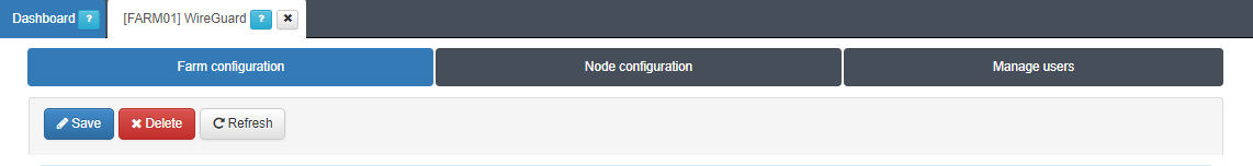
3.1.9.3.6.1. Farm configuration
The Farm configuration tab allows you to configure tunnel settings and Dynamic VPN zones.
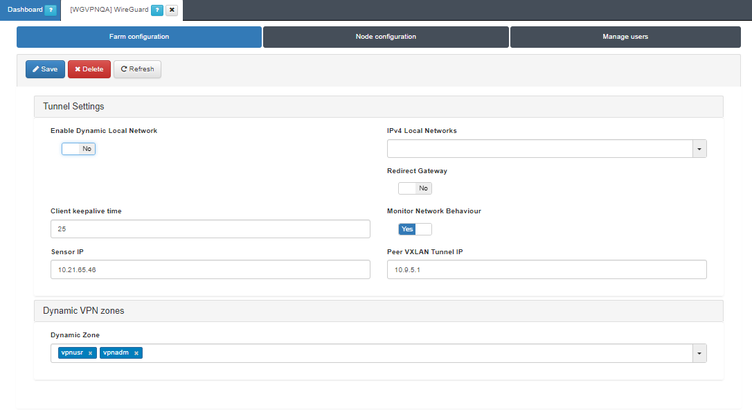
Tunnel Settings
Enable Dynamic Local Network: If the flag is enabled, VPN rules will be applied to route traffic.
Note
Enabling the Dynamic Local Network requires a VPN rule configuration. Refer to the Dynamic Route Configuration section for more information.
IPv4 Local Networks: Local networks in CIDR IPv4 format that can be accessed through the VPN. When the connection is established, the client receives the connection routes, enabling it to know which networks are accessible. It refers to the IP range that will be configured in the WireGuard configuration file (AllowedIps). This range determines the set of IP addresses that clients connecting to the VPN can access.
Client keepalive time: How often a keepalive packet is sent to keep the connection active (in seconds). We recommend to use 25 seconds.
Redirect Gateway: Flag to enable Gateway redirection. Enabling it changes the the IPv4 Local Networks to 0.0.0.0/0.
Monitor Network Behavior: If enabled, the traffic that is passing through the VPN connection will be monitored. Enabling it, displays the following fields.
Sensor IP: : IP address for the ON Sensor BackEnd (the sensor external IP).
Peer VXLAN Tunnel IP: Remote IP address for the ON Sensor BackEnd inside the VXLAN tunnel for traffic monitoring. It is recommended to use the 192.168.70.1, but other IP addresses could also be used. Note that the Peer VXLAN Tunnel IP must match the IP address assigned to the sensor’s VXLAN-TAP interface.
Dynamic VPN zones
Dynamic zone: Zones that will be dynamically associated to the VPN access groups. They will be used in the access policies.
Warning
Make sure to click on the Save button to apply the configuration.
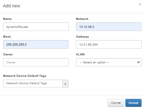
3.1.9.3.6.1.1. Dynamic Route Configuration
Enabling the Dynamic Local Network requires a VPN rule configuration. Follow the steps described in this section for configuring it:
Define a network for the dynamic routes in the ON CMD > Networks section.
Define a host object for the dynamic route under the network you have previously defined in the VPNGW > CMDB > Objects section.
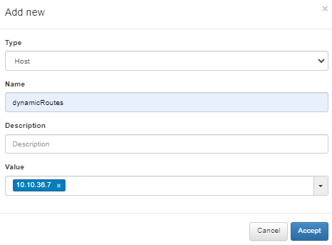
Create a VPNGW Rule allowing connections from a dynamic zone to the specified destination.
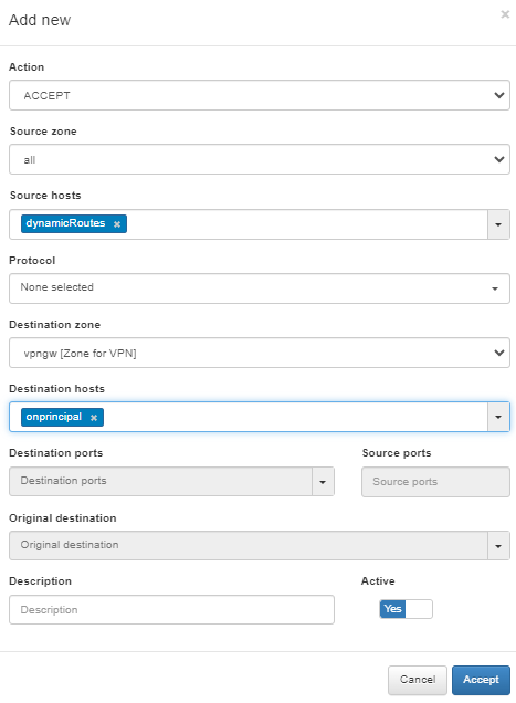
This rule will be applied when you use the Enable Dynamic Local Network flag.
3.1.9.3.6.2. Node configuration
The Node configuration tab allows you to configure WireGuard nodes.
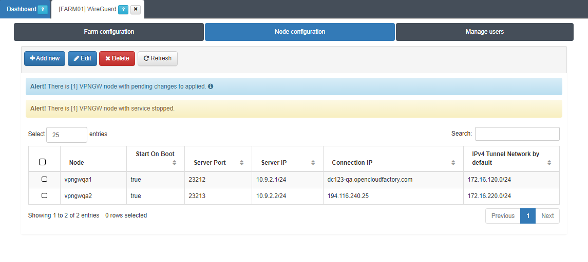
By clicking on the Add new button, it will display the following configuration window:
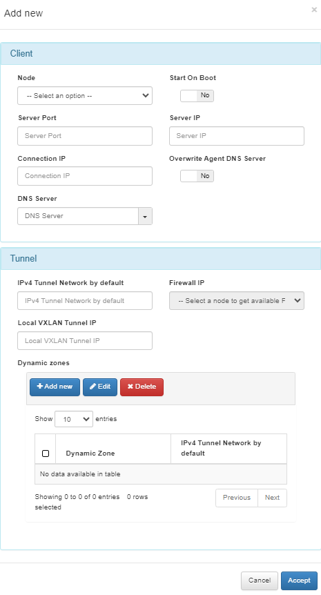
Client
Node: Select in which node you are going to apply the configuration.
Start On Boot: Enable this flag if you want the VPN Gateway to start when the machine reboots. If it is disabled, you have to manually start the VPN after rebooting.
Server Port: Port that is listening inside the Firewall to receive new connections.
Server IP: The IP to use on the WireGuard network interface on the VPN Gateway server. It is recommended to use the 192.168.71.1/24, but other IP addresses could also be used.
Connection IP: VPNGW node public IP (ON VPNGW node external IP).
Overwrite Agent DNS Server: By enabling the flag, the new DNS servers will replace the current ones. If disabled (default), the new DNS servers will be appended to the existing ones.
DNS Server: DNS server IP.
Tunnel
IPv4 Tunnel Network by default: Network in IPv4 CIDR format for remote users. Pool of IP addresses to be offered from the VPN Gateway. This network must be unique in your organization.
Firewall IP: The IP that has communication with the sensor.
Local VXLAN Tunnel IP: This has to be an IP address from the network of the VXLAN-TAP interface of the sensor.
Dynamic zones: This subsection allows you to assigning an IPv4 Tunnel Network by default to a dynamic zone.
To understand the configuration of the Sensor interface, refer to the ON Sensor Node configuration for the 2SRA use case.
3.1.9.3.6.3. Manage users
The Manage users tab allows you to monitor VPN users filtering by Node:
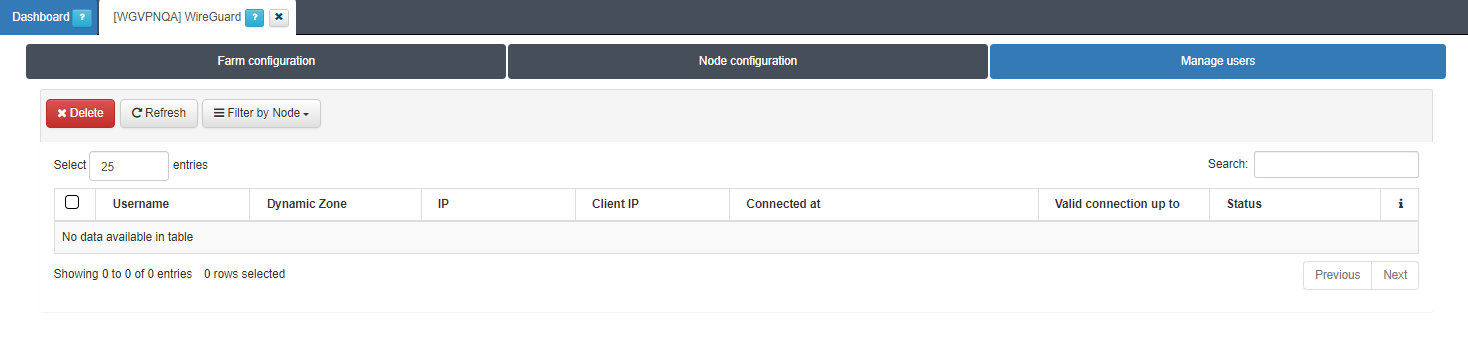
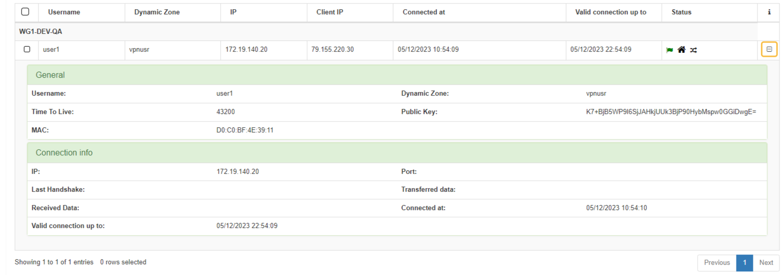
This view provides an organized display of information for all users connected through WireGuard:
Username: User identification.
Dynamic Zone: Network segment to which the user is connected.
IP: User IP address.
Client IP: Client IP address.
Connected at: Date when the user’s connection was established.
Valid connection up to: connection expiration time represented as a timestamp.
Status: icons that indicate the current connection status of the user.
If you click the + icon located at the end of a connection row, it will display expanded information about this connection.
The Search box allows you to search for any user data. For example, you can filter by the username user_test and as a result, a single row will appear with the user user_test.
Note
Users can establish multiple WireGuard sessions simultaneously across different devices using the same identity. If it happens, you will see the same user name displayed with different IPs in this view.