4.7.1.5. VPN Gateway
This section explains how to configure the VPNGW for the 2SRA use case.
4.7.1.5.1. Populating the VPNGW’s CMDB
The VPNGW’s CMDB can store a variety of objects, which can then be accessed and utilized across other sections of the Administration Portal.
To create VPN Gateway objects, navigate to VPNGW > CDMD > Objects.
This section presents a window with a wide range of predefined objects, primarily protocols. Here, you can create and manage these objects efficiently.
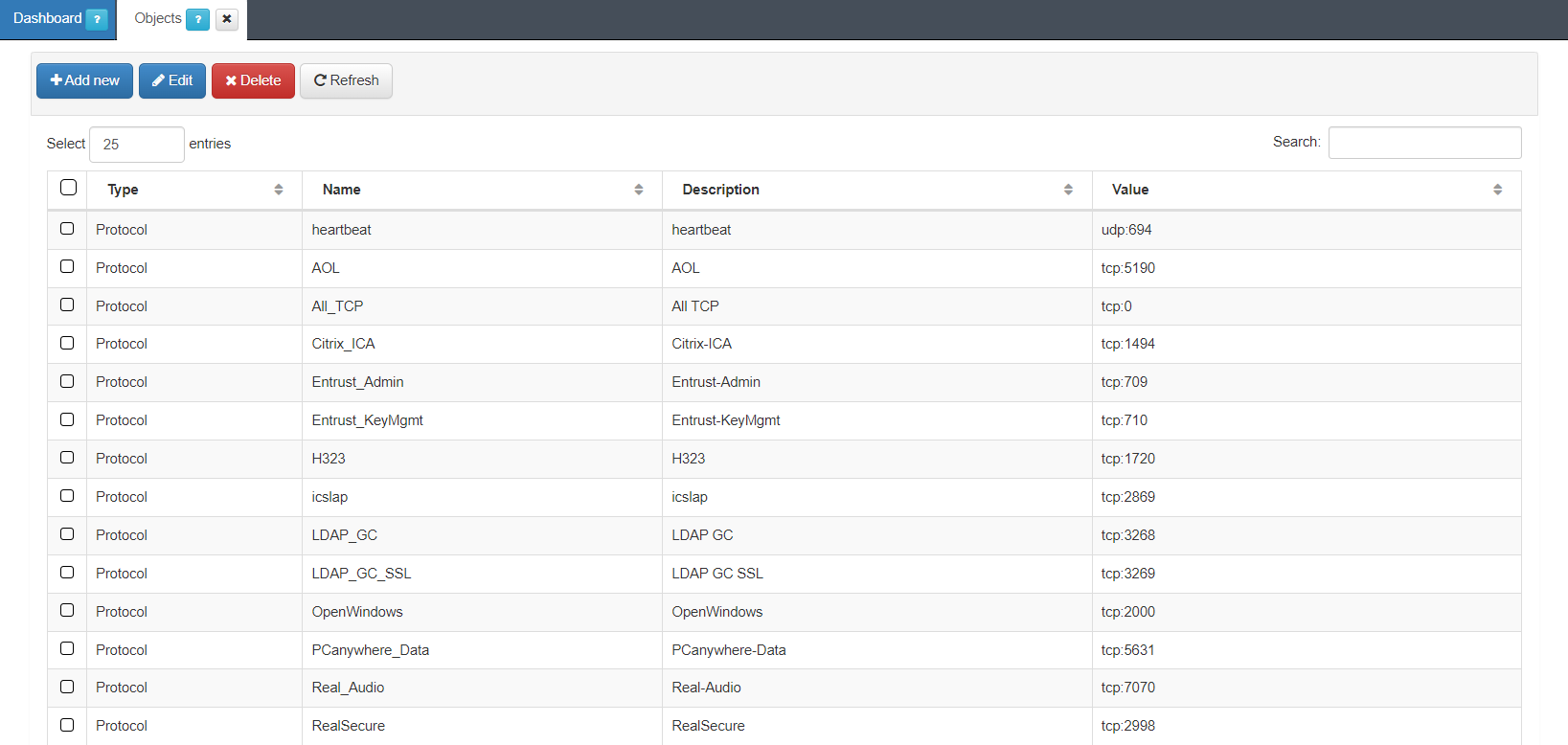
To create a new object, click on the Add new button:
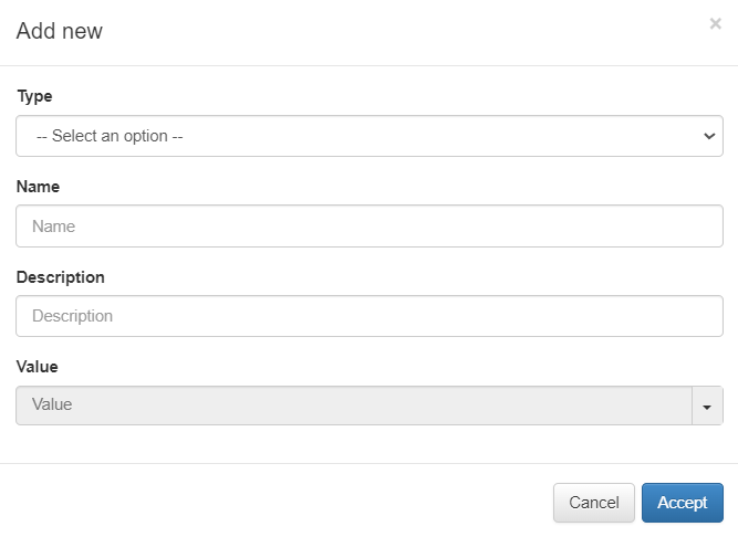
Type: Object type:
Network: One network. Ex: 172.16.1.0/24
Host: One concrete host. Ex: 172.16.1.13
Hosts: A list of hosts or IPs separated by commas.
Protocol: One protocol. Ex: tcp: 443
Protocols: A list of protocols separated by commas.
Name: Object identifier name. It should start with a letter, followed by any alphanumeric character or underscore.
Description: Here you can add a description of the object.
Value: Choose an object value from the dropdown menu. For instance, heartbeat [udp:694], AOL [tcp:5190], AII_TCP [tcp:709], Entrust_KeyMgmt [tp:710].
Later on, we will configure a rule in the VPNGW using the object we have created, and the variable that we have created can be used to configure these rules.
You can also Edit and Delete objects using the correspondent buttons located on the top row of this view.
The Search field located at the upper right corner of the view, allows you to search by type, name, description, or value.
4.7.1.5.2. ON VPNGW Configuration
The ON VPNGW node configuration takes place in the Administration Platform.
The following topics will detail how to configure zones, interfaces, policies, rules and hosts.
Refer to the VPNGW Administration Portal section for detailed information about its capabilities.
4.7.1.5.3. VPNGW Zones
You can locate the zone management section under VPNGW > FARM (previously created) > Zones.
The VPN Gateway serves as both a Layer 3 Firewall and a means to manage traffic flows within the VPN tunnel. The initial step involves identifying and configuring different zones within your network, which facilitates effective traffic management for the VPN. An example of network segmentation could be, Servers Zone, Servers DMZ, Corporate Firewall, and Frontend Firewall. include CMI architecture image updated
To ensure communication between the frontend and the zones of standard and critical servers, the traffic passes through the Corporate Firewall. As a result, these zones will be considered subzones of the previous zone. To achieve this configuration, you need to create these zones and subzones within the zone management section
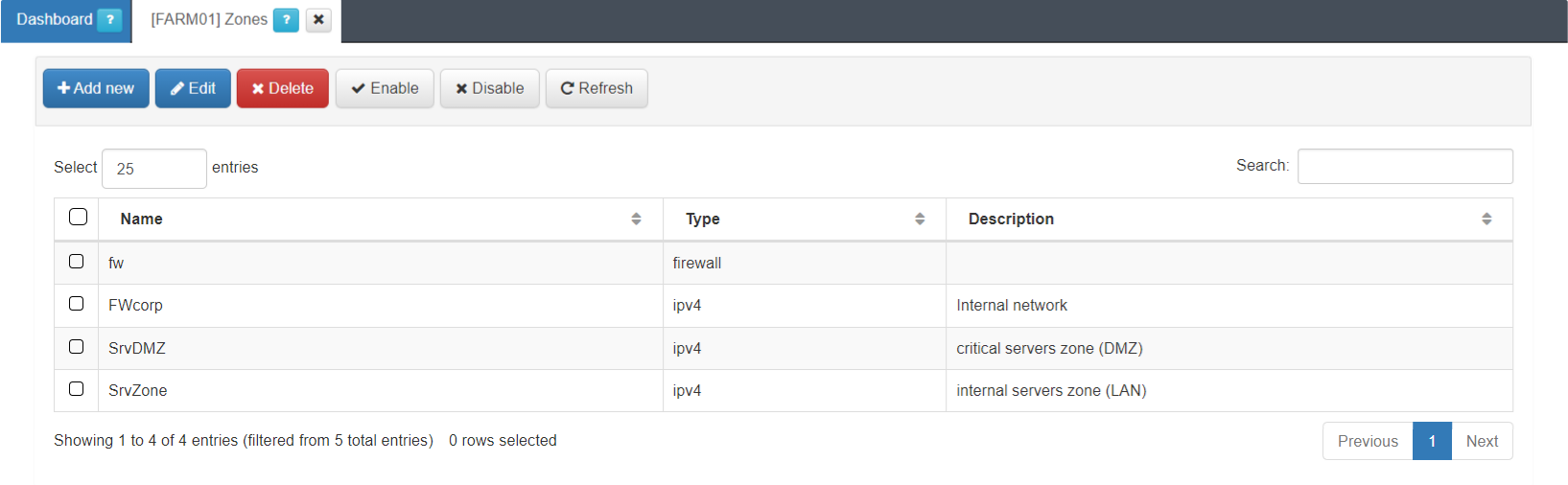
This view displays the zone name, its type and description.
The firewall (fw) zone itself is already created by default.
You can create the rest of zones by clicking on the Add new button. It will display the following configuration window:
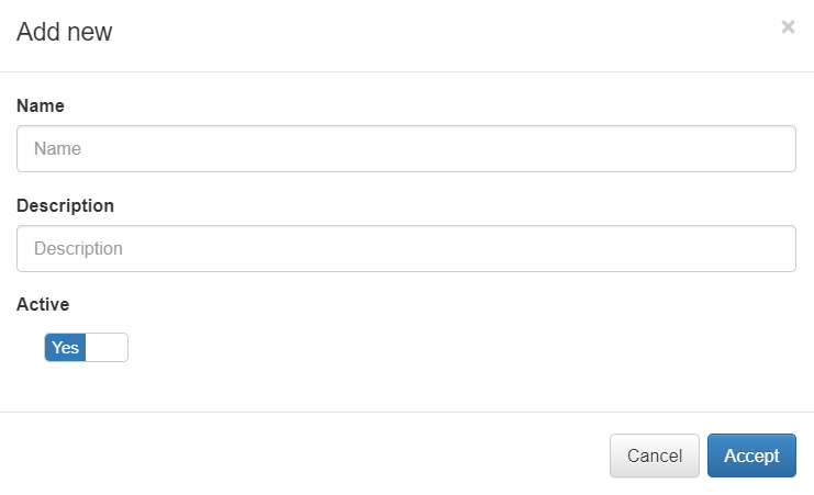
Name: The zone identification name must start with a letter followed by alphanumerical characters or underscore. It must have a maximum of 8 characters. Example: “FWCorp”
Description: Here you can add a Zone description.
Active: Flag to enable or disable the zone.
From this section, you can Enable and Disable a zone.
Note
By disabling a zone, all of its related objects and the related objects of its subzones will be disabled.
Similarly, enabling a zone will also enable its associated objects and those of its subzones.
After creating the zones, you need to assign them to a network interface (except for the default fw zone). See the next section for interface configuration.
4.7.1.5.4. VPNGW Interfaces
You can locate the interfaces management section under VPNGW > FARM (node that was previously created) > Interfaces.
Let’s use the example of the FWCorp zone previously created. Assign this zone to the FE network, by clicking on the Add new button. It will display the following configuration window:
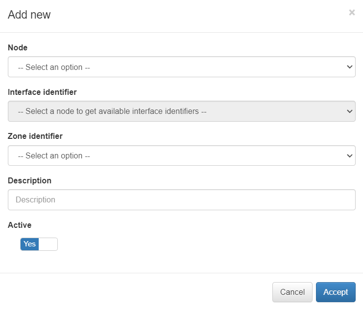
Node: Select the node for the new interface.
Interface identifier: Network interface with the main zone to associate.
Zone identifier: The zone that we want to associate to the interface.
Description: Descriptive comment.
Active: Flag to enable or disable the interface.
In this example we select the only existing network interface, the FWCorp zone and save by clicking on the Accept button.
4.7.1.5.5. VPNGW Hosts
Previously, we have assigned the “FWCorp” zone to the VPN Gateway network interface. The host identification (in terms of subnets and/or individual IP addresses) is used to distinguish server subzones from the FWCorp zone.
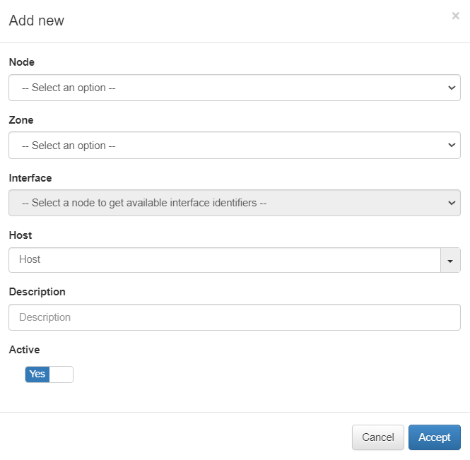
You can locate the Hosts management section under VPNGW > FARM (node that was previously created) > Hosts.
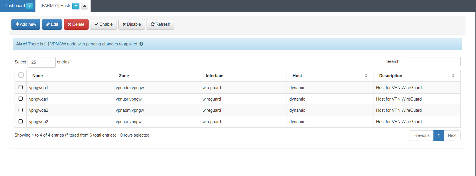
This view displays the Node, Zone, Interface, Host, and Description fields.
By clicking on the Add new button, it will display the following window:
Node: Select the host node.
Zone: Select a zone for VPN.
Interface: Choose an interface according to the selected node.
Host: Select a host.
Description: Add a description to the host.
Active: Flag to enable or disable the host.
You can also edit, delete, enable, and disable policies using the correspondent buttons located at the top row of this view.
4.7.1.5.6. VPNGW Policies
Policies define the connections between previously defined zones at a high level. Initially, you need to create a policy that denies traffic between all defined zones. Later, you can open the traffic according to your convenience.
You can locate the policies management section under VPNGW > FARM (node that was previously created) > Policies.
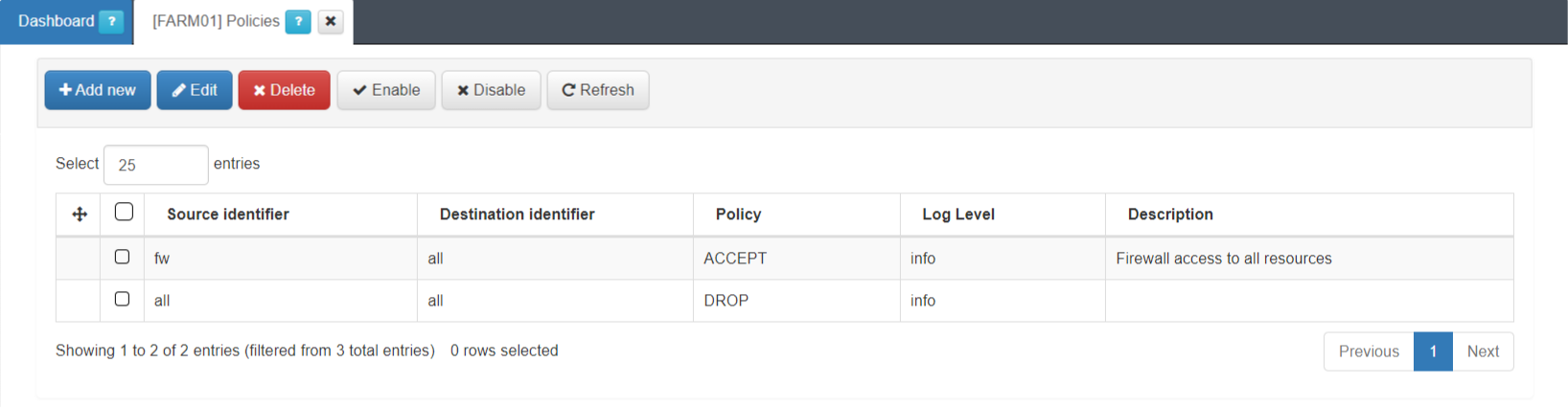
This view displays the Source identifier, Destination identifier, Policy, Log Level and description fields.
You can create a new policy by clicking on the Add new button. It will display the following configuration window:
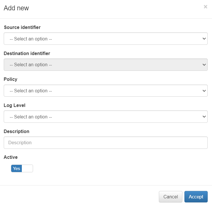
Source identifier: Zone from which the communication occurs.
Destination identifier: Zone to which the communication occurs.
Policy: Action we want to perform with the communication.
Log Level: Select the log level.
Description: Description of the policy
Active: Flag to enable or disable the interface.
In our example, we created a policy from all the zones to all the zones with the action of discarding (DROP) the communication.
You can also edit, delete, enable, and disable policies by using the correspondent buttons located at the top row of this view.
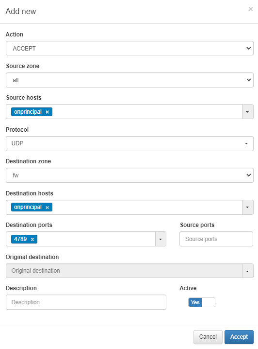
4.7.1.5.7. VPNGW Rule
To allow VPN traffic monitoring, you need to create a rule that accepts UDP port 4789 traffic from any zone to the firewall.
You can locate the rules management section under VPNGW > FARM (node that was previously created) > Rules.
Create a new rule by clicking on the Add new button, and use the parameters shown in the following image:
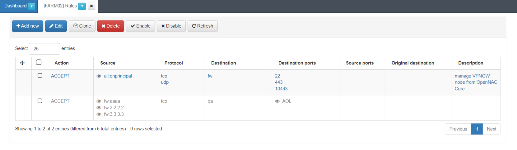
In the following image you can see other rules examples:
4.7.1.5.8. WireGuard
To configure WireGuard, you need to apply the Farm configuration and the Node configuration.
4.7.1.5.9. Farm configuration
The Farm configuration tab allows you to configure tunnel settings and Dynamic VPN zones.
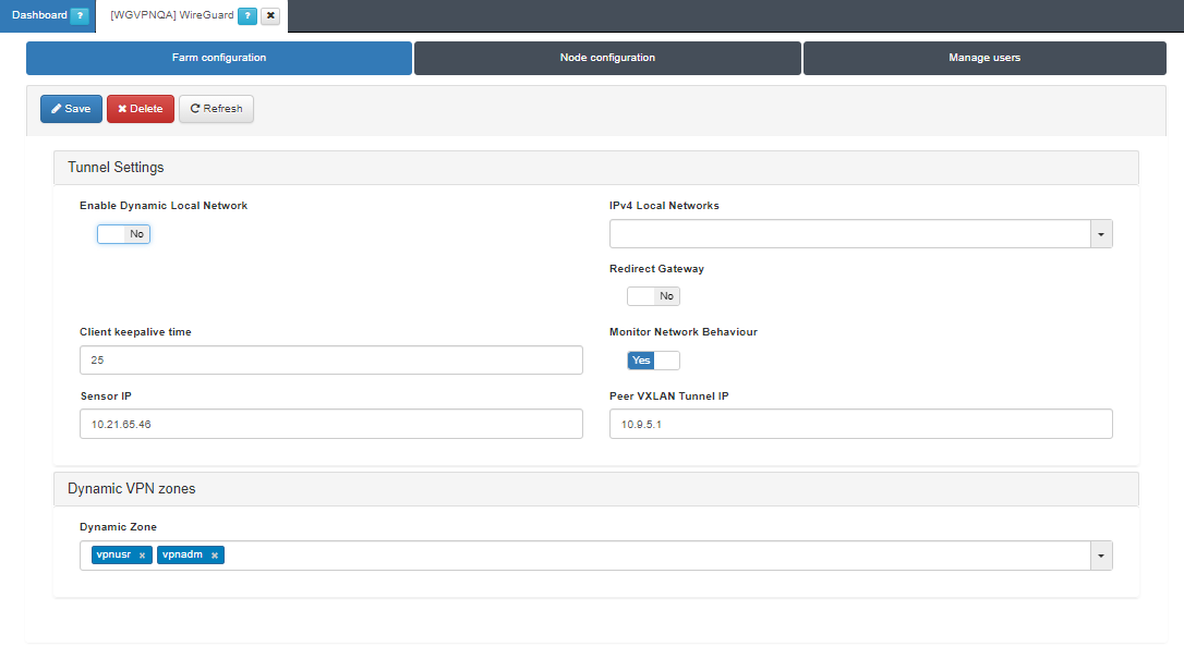
Tunnel Settings
Enable Dynamic Local Network: If the flag is enabled, VPN rules will be applied to route traffic.
Note
Enabling the Dynamic Local Network requires a VPN rule configuration. Refer to the Dynamic Route Configuration section for more information.
IPv4 Local Networks: Local networks in CIDR IPv4 format that can be accessed through the VPN. When the connection is established, the client receives the connection routes, enabling it to know which networks are accessible. It refers to the IP range that will be configured in the WireGuard configuration file (AllowedIps). This range determines the set of IP addresses that clients connecting to the VPN can access.
Client keepalive time: How often a keepalive packet is sent to keep the connection active (in seconds). We recommend to use 25 seconds.
Redirect Gateway: Flag to enable Gateway redirection. Enabling it changes the the IPv4 Local Networks to 0.0.0.0/0.
Monitor Network Behavior: If enabled, the traffic that is passing through the VPN connection will be monitored. Enabling it, displays the following fields.
Sensor IP: : IP address for the ON Sensor BackEnd (the sensor external IP).
Peer VXLAN Tunnel IP: Remote IP address for the ON Sensor BackEnd inside the VXLAN tunnel for traffic monitoring. It is recommended to use the 192.168.70.1, but other IP addresses could also be used. Note that the Peer VXLAN Tunnel IP must match the IP address assigned to the sensor’s VXLAN-TAP interface.
Dynamic VPN zones
Dynamic zone: Zones that will be dynamically associated to the VPN access groups. They will be used in the access policies.
Warning
Make sure to click on the Save button to apply the configuration.
4.7.1.5.9.1. Dynamic Route Configuration
Enabling the Dynamic Local Network requires a VPN rule configuration. Follow the steps described in this section for configuring it:
Define a network for the dynamic routes in the ON CMD > Networks section.
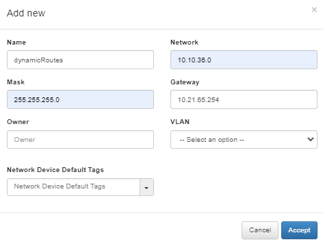
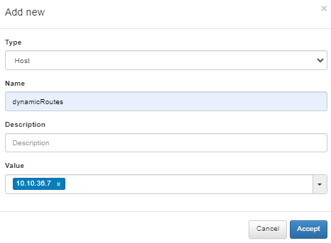
Define a host object for the dynamic route under the network you have previously defined in the VPNGW > CMDB > Objects section.
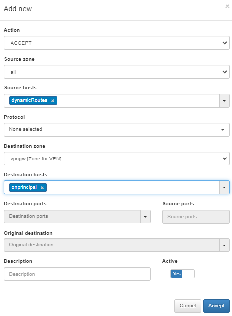
Create a VPNGW Rule allowing connections from a dynamic zone to the specified destination.
4.7.1.5.10. Apply Firewall Configurations
Once you have finished all the previous configurations, you will be able to Start the WireGuard service.
Open the VPNGW > Manage VPNGW section located on the main menu. Select the configured node, click on the correspondent service, in our example we will use the Manage WireGuard button, and select Deploy & restart. A pop-up window will be displayed reporting on the status of the various processes that will execute before starting the WireGuard service. It will also report any warnings or errors.
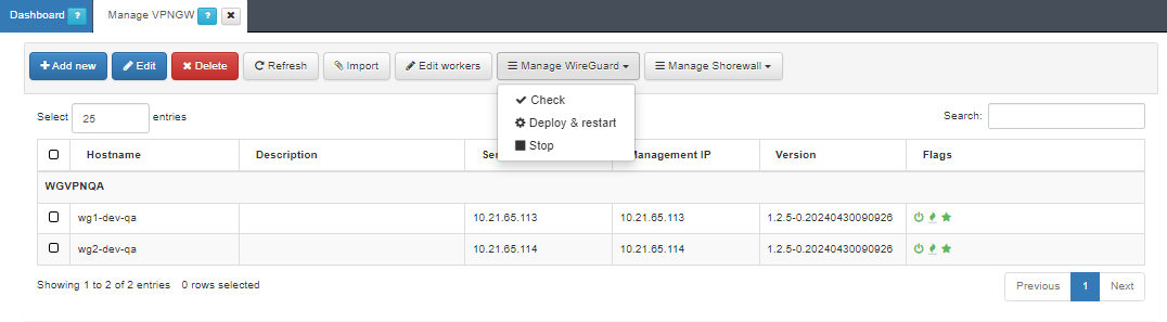
Initially the three flags displayed in this view will be in red.
The first icon, refers to VPNGW up and running.
The flame, refers to the Shorewall service.
The star, refers to WireGuard.
If the deployment and restart of the services are OK, they will change their color status to green.