BASIC LAB DEPLOYMENT
STEP 1. REQUIREMENTS
Hardware Requirements
BASIC LAB computer:
- Hard Disk Space= 100G
- Memory= 16G
- Processors= 8 core processor
- 3 USB Ports
- 1 Physical network adapter
Note
We recommended install an solid state drive SSD for increase the computer performance
- Switch (8 ports)
Note
Is recommended to use Cisco switch, this you should use Cisco IOS 12.2.55 or higher
- 4 UTP LAN wire (Length 1m)
- 3 USB Adapter Network. We have used this.
Note
In Windows clients is being detected problems with interfaces managed by the operating system, VLAN tags are dropped by host machine. is strongly recommended to assign USB to Network interfaces to the virtual machine to avoid these problems.
Software Requirements
- Virtual Box Software available.
- Virtual Box Extension Pack.
- Latest OVA image for Core
- Latest OVA image for Sensor
- Latest OVA image for Analytics
- ISO Windows Server 2012 R2
- ISO for Client PC, all the configuration are tested with Windows 10.
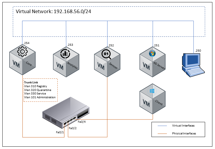
STEP 2. TOPOLOGY
The initial configuration will be based in 5 virtual machines installed over Virtual Box software, additional you should have an 8 port switch. The 5 virtual machines will be set on the student computer, so you have to be sure to use an appropriate machine as minimal requirement indicate.
STEP 3. CONSIDERATIONS
IP Addressing
Basic LAB Virtual Network As shown in the topology is required to have a virtual network to communicate every node.
| Host | IP Address | Network Mask |
|---|---|---|
| Network IP | 192.168.56.0 | 255.255.255.0 |
| Core | 192.168.56.254 | 255.255.255.0 |
| Analytics | 192.168.56.253 | 255.255.255.0 |
| Sensor | 192.168.56.252 | 255.255.255.0 |
| AD | 192.168.56.251 | 255.255.255.0 |
Basic LAB Switch VLANs As shown in the topology the next chart shows the VLANs configuration.
| Network | Description | Network IP | Network Mask | IF Switch IP | Core IP |
|---|---|---|---|---|---|
| VLAN101 | Management | 192.168.101.0 | 255.255.255.0 | 192.168.101.1 | 192.168.10.254 |
| VLAN310 | Registry | 192.168.10.0 | 255.255.255.0 | 192.168.10.1 | 192.168.10.254 |
| VLAN320 | Quarantine | 192.168.20.0 | 255.255.255.0 | 192.168.20.1 | 192.168.20.254 |
| VLAN330 | Service | 192.168.30.0 | 255.255.255.0 | 192.168.30.1 | 192.168.30.254 |
STEP 4. QUICK START
Installing Virtual Box
Download and install virtual Box and follows the following steps.
Installing ON Core
- Connect the first USB network adapter, be sure that the local system recognizes it.
- Open Virtual Box on your computer
- Import ON Core OVA to Virtual Box and set the following parameters as follows
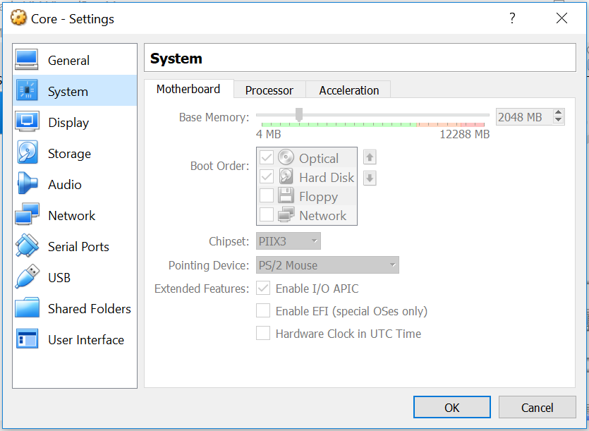
- Select the Core Machine and go to settings icon
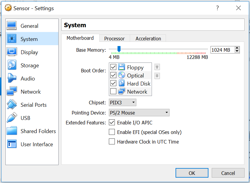
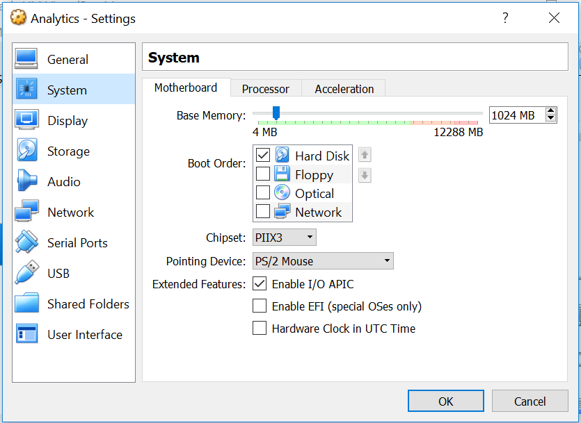
- Go to system Window in motherboard tab and set the memory parameter in 2G
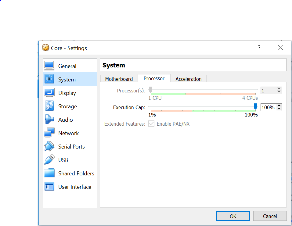
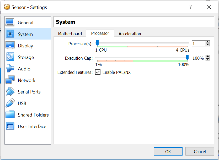
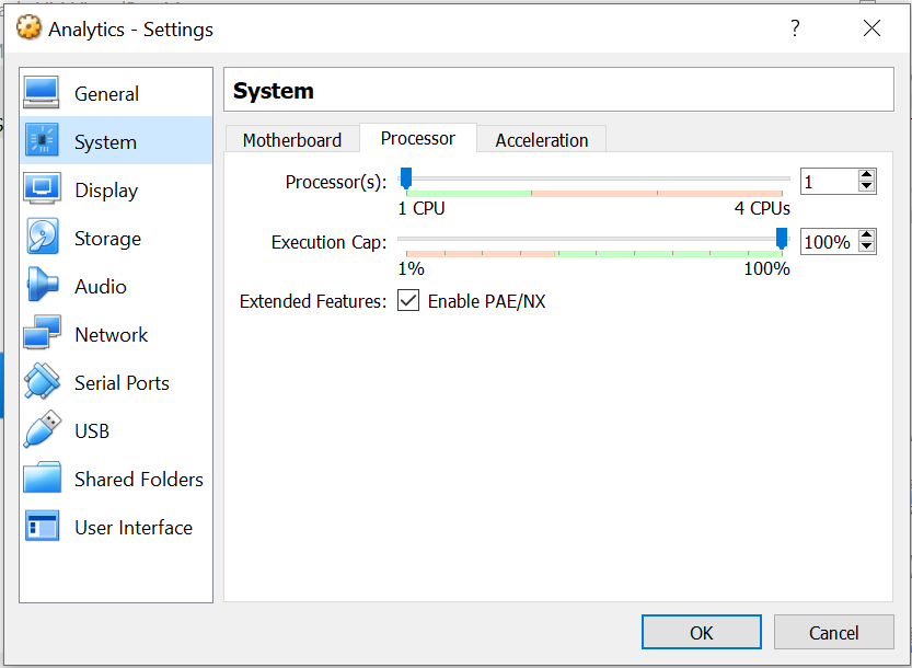
- In processor tab set the Processor(s) parameter in 1
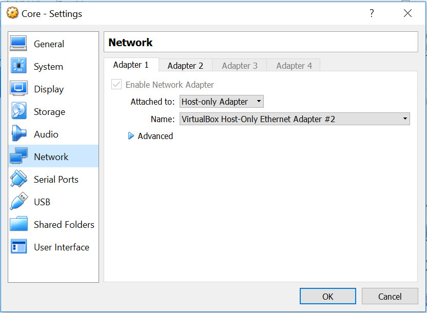
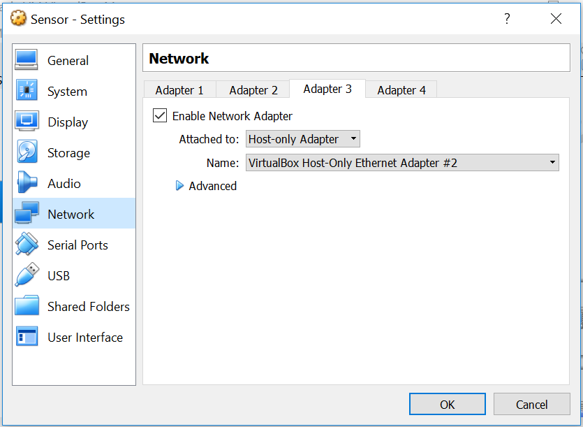
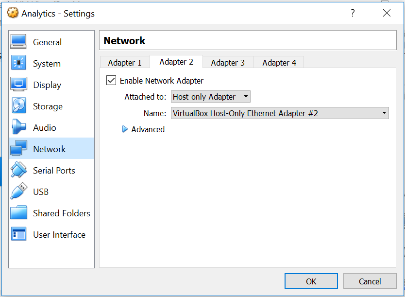
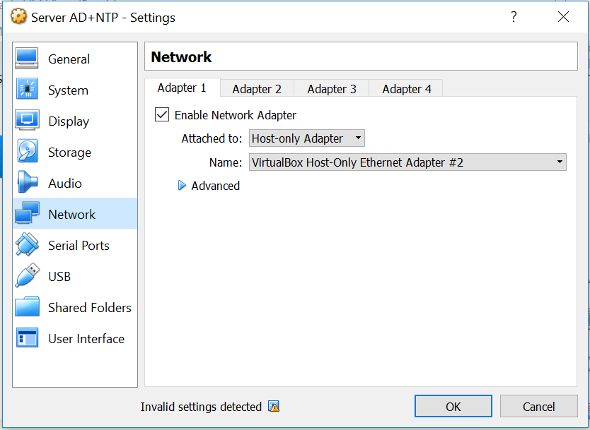
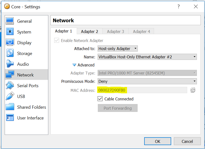
- Go to Network option, set one network adapter, check enable network adapter box, select Host-only Adapter
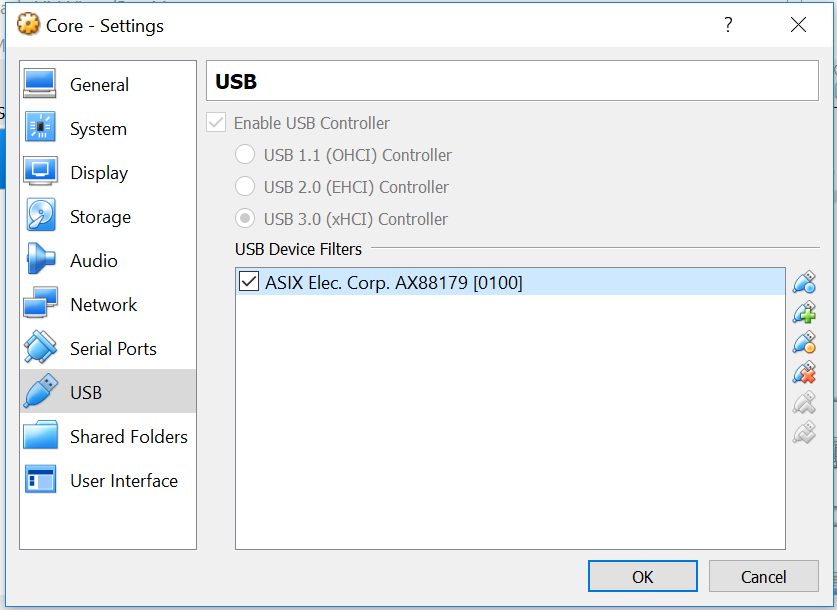
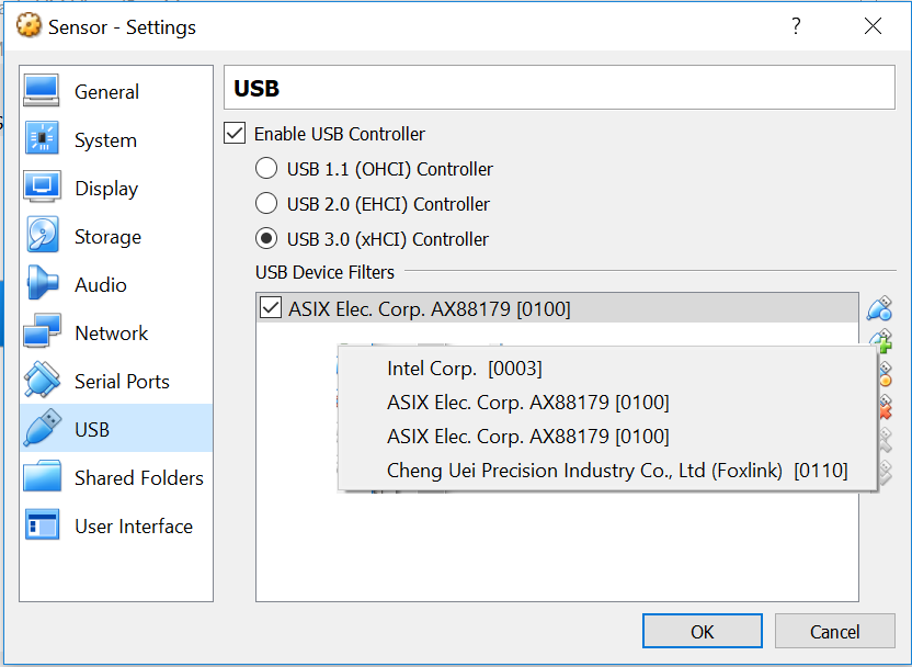
- Go to USB option, check enable USB controller box, select USB 3.0, use the + icon and add the USB network adapter
- Turn on the ON Core
Installing ON Sensor
- Connect the second USB network adapter, be sure that the local system recognizes it.
- Open Virtual Box on your computer
- Import ON Sensor OVA to Virtual Box
- Select the Core Machine and go to settings icon
- Go to system Window in motherboard tab and set the memory parameter in 1G
- In processor tab set the Processor(s) parameter in 1.
- Go to Network option, set one network adapter, check enable network adapter box, select Host-only Adapter
- Go to USB option, check enable USB controller box, select USB 3.0, use the + icon and add the USB network adapter. Select a different USB network adapter than the one you have used before for ON Core.
- Turn on the ON Sensor
Installing ON Analytics
- Open Virtual Box on your computer
- Import ON Analytics OVA to Virtual Box
- Select the Analytics Machine and go to settings icon
- Go to system Window in motherboard tab and set the memory parameter in 1G
- In processor tab set the Processor(s) parameter in 1.
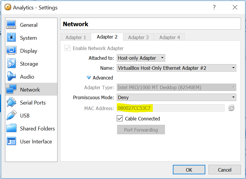
- Go to Network option, set one network adapter, check enable network adapter box, select Host-only Adapter.
- Turn on the ON Analytics
Active Directory Server
At this point you will have to add an AD server to Virtual Box, with just one network adapter, the server will be connected to ON Core through this virtual interface.
- Connect the second USB network adapter, be sure that the local system recognizes it.
- Open Virtual Box on your computer
- Open the Windows Server machine on Virtual Box
- Go to Network option, set one network adapter, check enable network adapter box, select Host-only Adapter.
For this Step you can use an ISO or install and configure windows server, we recommend install a Windows server 2012 R2 over a virtual machine; however, is your choice. You can download the Windows server 2012 R2 from Microsoft website:
Windows server 2012 R2 download.
You can follow the recommended steps for configure the AD Server.
Note
Also you should enable the NTP service on the AD Server, because this machine is going to be the NTP server in our lab, you can check the next link for review the configuration needed.
Installing Windows Client
At this point you will have to add a windows client to Virtual Box, with just one network adapter and this is going to be used for testing, you have to use a physical interface to connect the client to switch so use an USB network adapter.
- Connect the third USB network adapter, be sure that the local system recognizes it.
- Open Virtual Box on your computer
- Open the Windows client machine on Virtual Box
- Select the Windows Client and go to settings icon
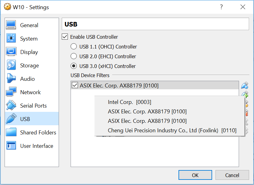
- Go to USB option, check enable USB controller box, select USB 3.0, use the + icon and add the USB network adapter. Select a different USB network adapter than the one you have used before for ON Core, ON Sensor.
For this Step you can use an ISO or install and configure windows client, we recommend install a Windows 10 client over a virtual machine; however, is your choice.
You can download the Windws 10 from Microsoft website:
Get Access to Switch
Use a terminal console on the student machine for connect to switch. You can use the following but is your choice.
STEP 5. LAB SETTINGS
Note
Review use case requirements to progress, sometimes is not required to have all the nodes deployed (Core, Analytics, Sensor). for instance visibility use case doest need sensor deployment.
On Core
One USB network adapter should be connected to the student computer, attached to core machine. Turn the core on.
User: root
Password: opennac
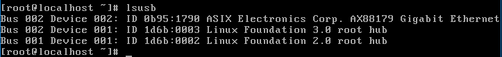
Verify that USB has been recognized by core using the command:
lsusb

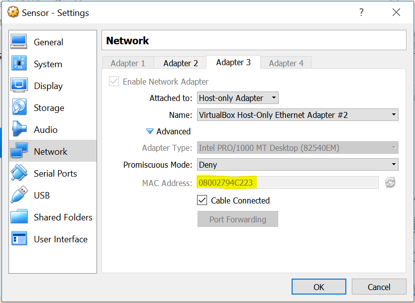
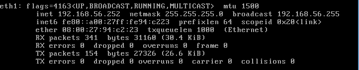
Verify that mac address associate to each network connection using the network settings machine and the ifconfig command
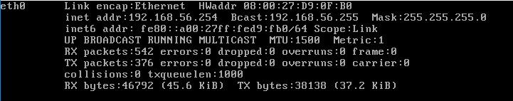
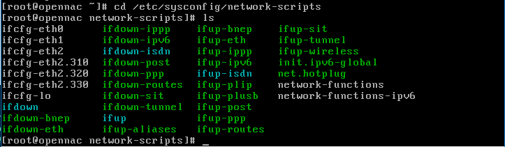
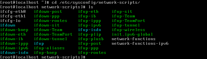
After identifying each connection, go to:
cd /etc/sysconfig/network-scripts/
List the file in this directory using the command:
ls
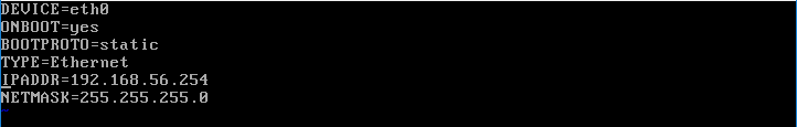
Configure the file associate to virtual interface using: Vim filename for virtual interface, for this case:
Vim ifcfg-eth0
Configure the file associate to physical interface, identify the USB network adapter mac address before configure it. You can verify the mac address using the command:
ip link show
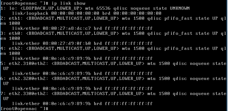
Vim filename for physical interface
Vim ifcfg-eth2

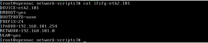
Configure the Vlan networks using sub-interfaces for the physical interface using the command: Vim filename for physical interface.101 // Administration Vlan
Vim ifcfg-eth2.101
Vim filename for physical interface.310 // Registry Vlan
Vim ifcfg-eth2.310

Vim filename for physical interface.320 // Quarantine VLan
Vim ifcfg-eth2.320

Vim filename for physical interface.330 // Service Vlan
Vim ifcfg-eth2.330

Use the command service network restart to apply the changes over the interfaces
service network restart
Use the command timedatectl for configure your timezone
timedatectl set-timezone Europe/Madrid
Now that we have IP connectivity with openNAC we can access to the Administration portal
Note
The URL https://ip_management/admin for Administration Portal
To basic wizard openNAC Core, please visit **openNAC Core Deployment Guide**, and follow the steps from the 3. Gaining Access to Administration Portal
To basic deploy and configure an openNAC Core, please visit **openNAC Core Deployment Guide**
On Sensor
A different USB network adapter than the one you have used before for ON Core should be connected to the student computer, attached to sensor machine. Turn the sensor on, verify that USB has been recognized by core using the command:
Verify that mac address associate to each network connection using the network settings machine and the ifconfig command
After identifying each connection, go to:
cd /etc/sysconfig/network-scripts/
List the files in this directory using the command:
ls
Configure the file associate to virtual interface using: Vim filename for virtual interface
Vim ifcfg-eth1
Use the command timedatectl for configure your timezone
timedatectl set-timezone Europe/Madrid
At this point no configuration needed for physical interface, this port is going to use as spam port.
- To deploy and configure openNAC Sensor, please visit **openNAC Sensor Deployment Guide**
On Analytics
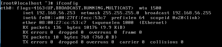
Turn the Analytics ON, verify that mac address associate to each network connection using the network settings machine and the ifconfig command
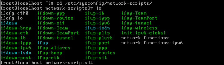
After identifying each connection, go to:
cd /etc/sysconfig/network-scripts/
List the files in this directory using the command:
ls
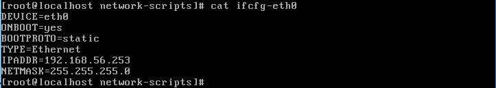
Configure the file associate to virtual interface using: Vim filename for virtual interface. For this case:
Vim ifcfg-eth0
Use the command timedatectl for configure your timezone
timedatectl set-timezone Europe/Madrid
Configure the API KEY
Go to Web Console, ON CMDB –> Security –> API Key. Select Add new option, insert the Analytics server IP address and accept, a key will be generate.
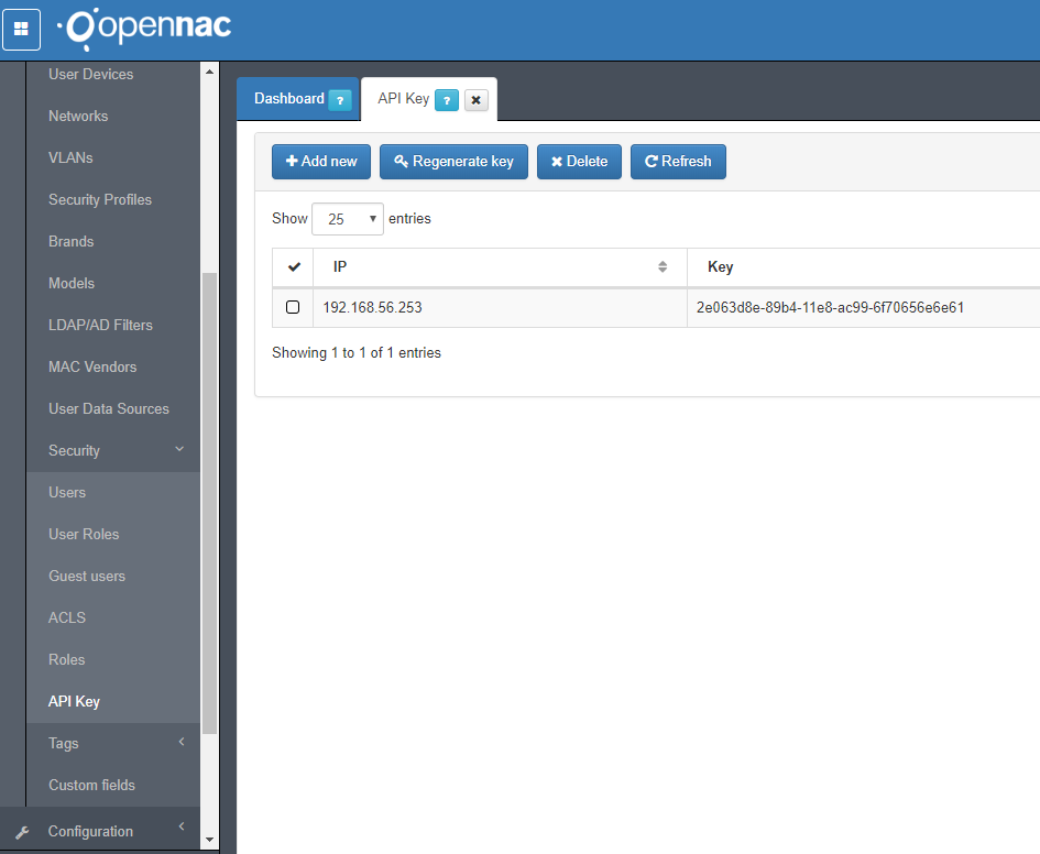
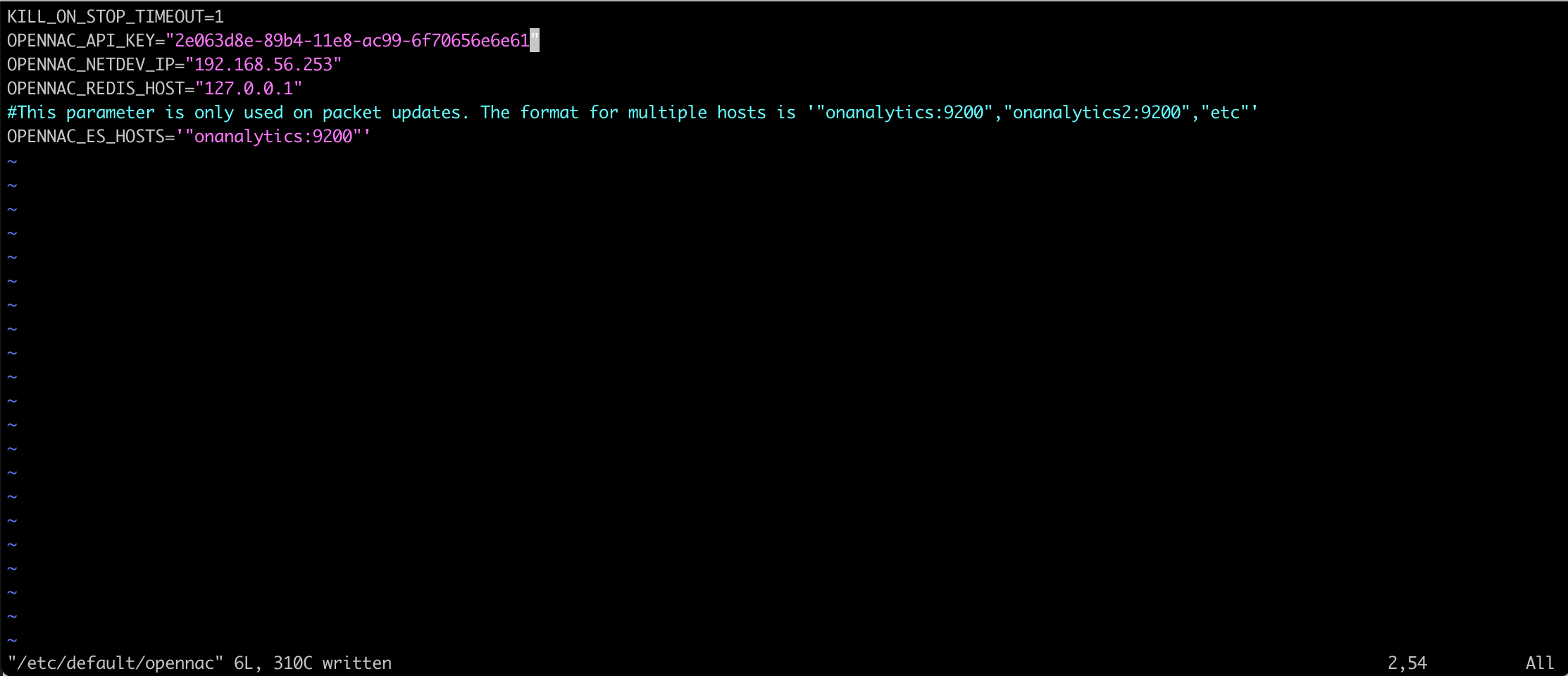
Copy the string key. Open the Analytics CLI and edit the file ‘opennac’ in the path /etc/default as follows. Insert the aggragator IP address, for this deploy the aggregator and the analytics are the same server so use its own IP address.
vim /etc/default/opennac
Restart the logstash service
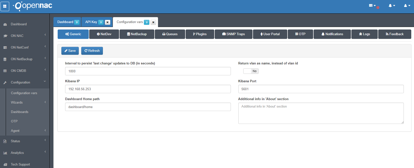
Specify the kibana IP address in openNAC web console. Cofiguration –> Configuration vars, Generic tab Kibana IP.
- To deploy and configure an openNAC Analytics, please visit **openNAC Analytics Deployment Guide**
On Switch
Configure the vlan settings in the appropriate configuration mode on switch
vlan 101
name Administration
interface vlan 101
ip address 192.168.101.1 255.255.255.0
exit

vlan 310
name DC_Registry
interface vlan 310
ip address 192.168.10.1 255.255.255.0
exit

vlan 320
name DC_Quarantine
interface vlan 320
ip address 192.168.20.1 255.255.255.0
exit

vlan 330
name DC_Service
interface vlan 330
ip address 192.168.30.1 255.255.255.0
exit
Configure the trunk settings in the appropriate configuration mode on switch
interface FastEthernet0/1
description "UPLINK"
switchport mode trunk
switchport nonegotiate
Note
Please don’t forget save the switch configuration using the command: Copy running-config startup config.
- To deploy and configure Cisco Switch 2960, please visit **Cisco configuration section**
- To deploy and configure 802.1x Supplicants, please visit **supplicant configuration section**
STEP 6. CONNECTIVITY TEST
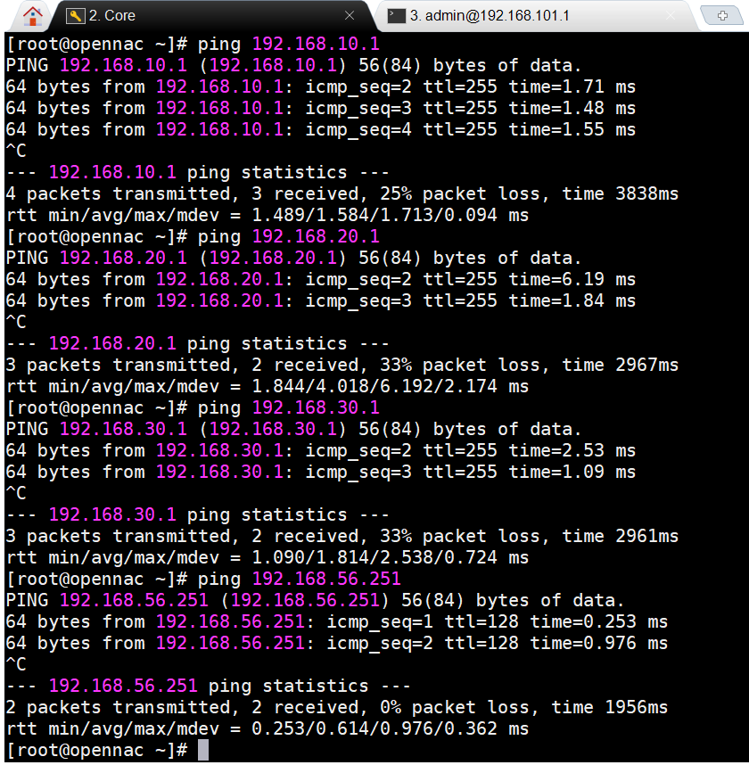
On Core
Connectivity test to hosts in virtual network
Connectivity test to each vlan
On Sensor
Connectivity test to hosts in virtual network
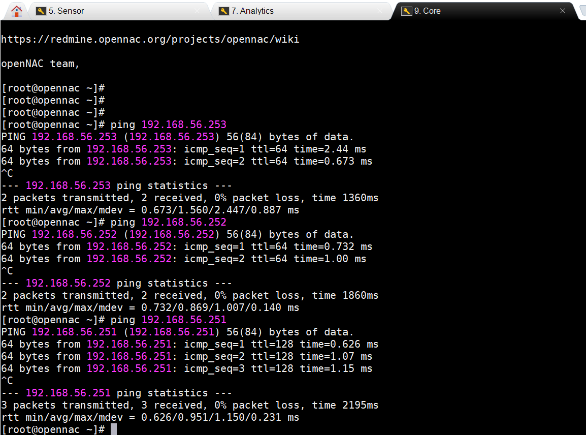
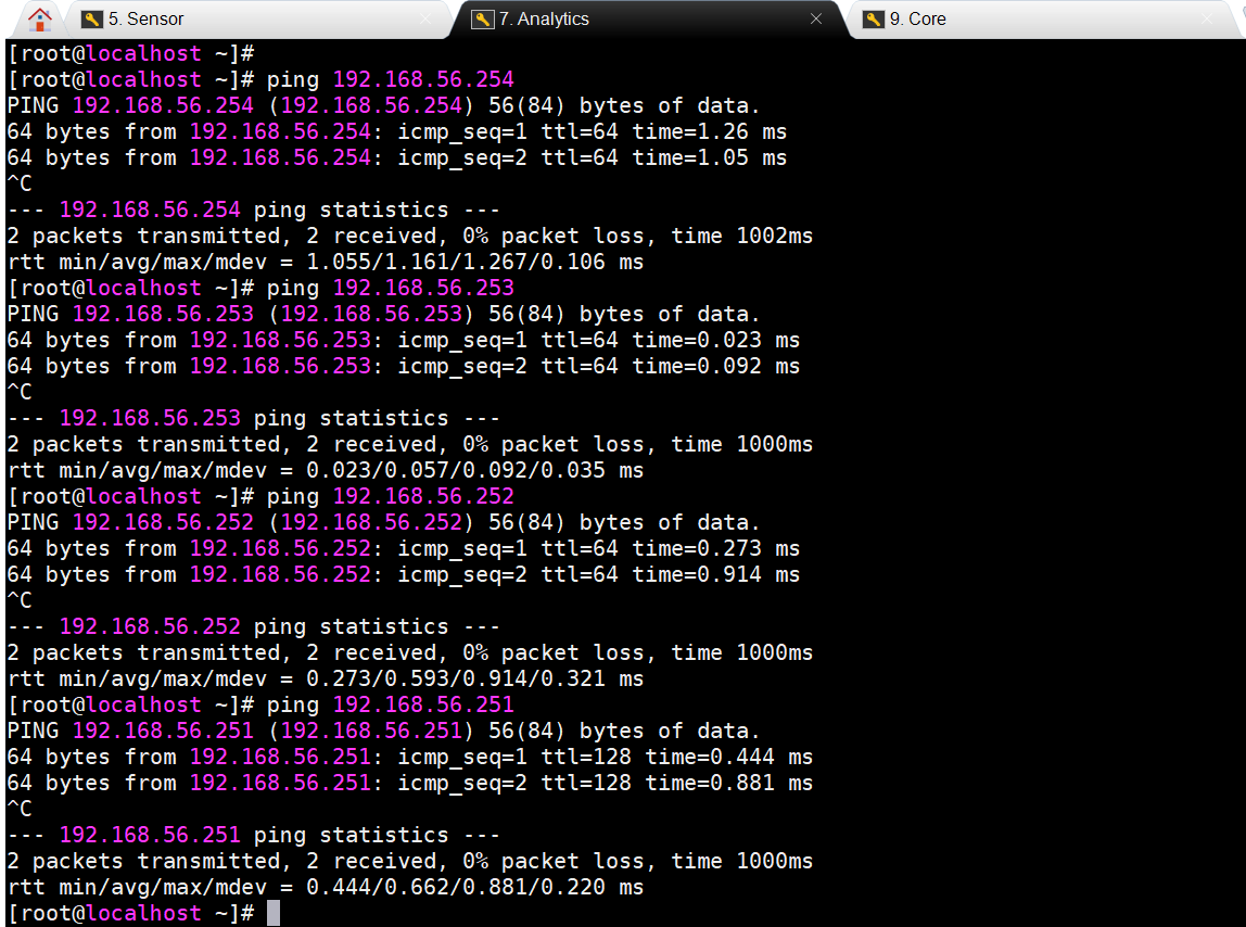
On Analytics
Connectivity test to hosts in virtual network
As soon as you complete this configuration guide and you reach any device on the basic lab, you will be ready now to start and configuring each use case.