4.7.1.5. VPN Gateway
This section explains how to configure the VPNGW for the 2SRA use case.
4.7.1.5.1. Populating the CMDB
Various objects can be stored in the CMDB of the VPNGW that can be used later in the FE.
To create VPN Gateway objects, use the Administration Portal main menu: VPNGW > CDMD > Objects. It displays a window with numerous predefined objects, mostly protocols. From this section you can create and manage objects.
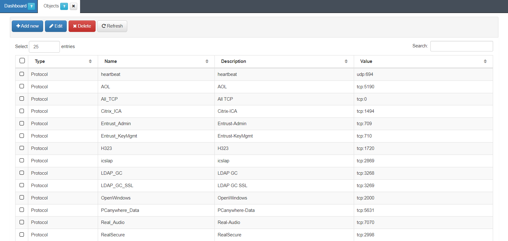
To create a new object, click on the Add new button:
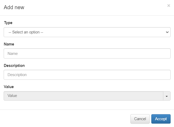
Type: Object type:
Network: One network. Ex: 172.16.1.0/24
Host: One concrete host. Ex: 172.16.1.13
Hosts: A list of hosts or IPs separated by commas.
Protocol: One protocol. Ex: tcp: 443
Protocols: A list of protocols separated by commas.
Name: Object identifier name. It should start with a letter, followed by any alphanumeric character or underscore.
Description: Here you can add a description of the object.
Value: Choose an object value from the dropdown menu. For instance, heartbeat [udp:694], AOL [tcp:5190], AII_TCP [tcp:709], Entrust_KeyMgmt [tp:710].
Later on, we will configure a rule in the VPNGW using the object we have created, and the variable that we have created can be used to configure these rules.
You can also edit and delete objects using the correspondent buttons located on the top row of this view.
The Search field located at the upper right corner of the view, allows you to search by type, name, description, or value.
4.7.1.5.2. VPN Gateway Configuration
This section explains how to configure the VPN Gateway.
4.7.1.5.2.1. Configuration of the HAProxy service
In this step, the HA Proxy service will be configured. This service is used to redirect web traffic from the VPN Gateway to the onprincipal module in the backend.
Edit the /etc/haproxy/haproxy.cfg file
In case you have not configured any certificate, the following lines must be commented out (add # at the beginning), this will force the use of port 80 for the connection:
#bind emmafront:443 ssl crt /etc/ssl/certs/cert_emma.pem no-sslv3 no-tlsv10 no-tls-tickets
#redirect scheme https code 301 if !{ ssl_fc }
#reqadd X-Forwarded-Proto:\ https
Remember to uncomment these lines after obtaining and configuring the certificate, so you can use port 443 with a server certificate.
To give permissions to access the administration panel from the public URL (not recommended) uncomment (remove # from the beginning) the following line:
#use_backend app if adminACL
Restart the service
systemctl restart haproxy
4.7.1.5.2.1.1. VPNGW node
The VPN Gateway node configuration happens in the Administration Platform.
In the following topics we will detail how to configure zones, interfaces, policies, rules and hosts.
See the VPNGW Administration Portal section for detailed information about this module.
4.7.1.5.3. VPNGW Zones
You can locate the zone management section by opening VPNGW > FARM (previously created) > Zones.
The VPN Gateway serves as both a Layer 3 Firewall and a means to manage traffic flows within the VPN tunnel. The initial step involves identifying and configuring different zones within your network, which facilitates effective traffic management for the VPN. An example of network segmentation could be, Servers Zone, Servers DMZ, Corporate Firewall, and Frontend Firewall. include CMI architecture image updated
To ensure communication between the frontend and the zones of standard and critical servers, the traffic passes through the Corporate Firewall. As a result, these zones will be considered subzones of the previous zone. To achieve this configuration, you need to create these zones and subzones within the zone management section
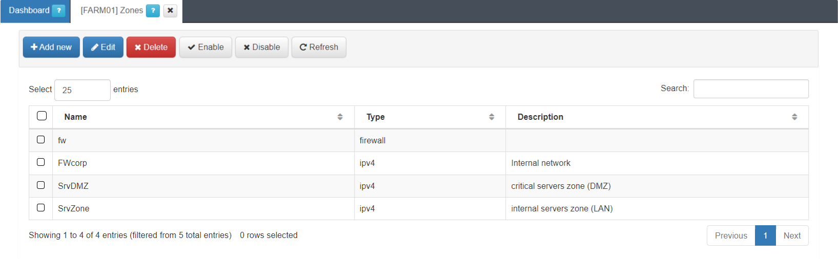
This view displays the zone name, its type and description.
The firewall (fw) zone itself is already created by default.
You can create the rest of zones by clicking on the Add new button. It will display the following configuration window:
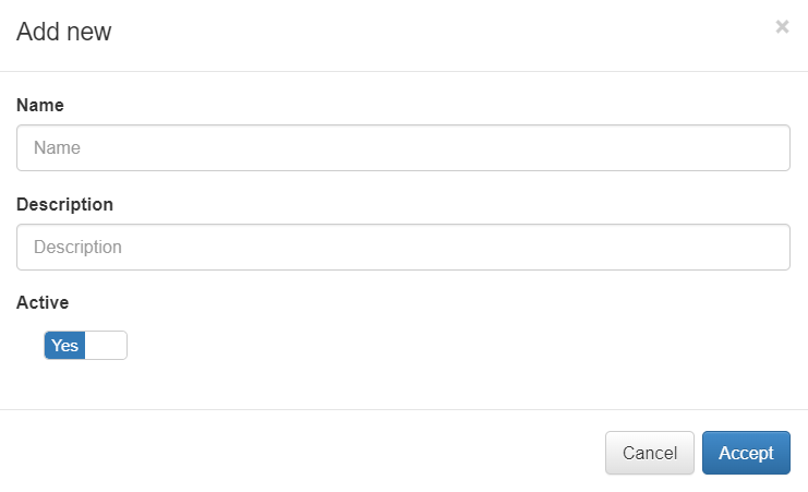
Name: The zone identification name must start with a letter followed by alphanumerical characters or underscore. It must have a maximum of 8 characters. Example: “FWCorp”
Description: Here you can add a Zone description.
Active: Flag to enable or disable the zone.
You can also edit, delete, enable, and disable zones using the correspondent buttons located at the top row of this view.
Once the zones are created, we have to assign them to a network interface (except the default fw zone).
4.7.1.5.4. VPNGW Interfaces
You can locate the interfaces management section by opening VPNGW > FARM (node that was previously created) > Interfaces.
Let’s use the example of the FWCorp zone previously created. Assign this zone to the FE network, by clicking on the Add new button. It will display the following configuration window:
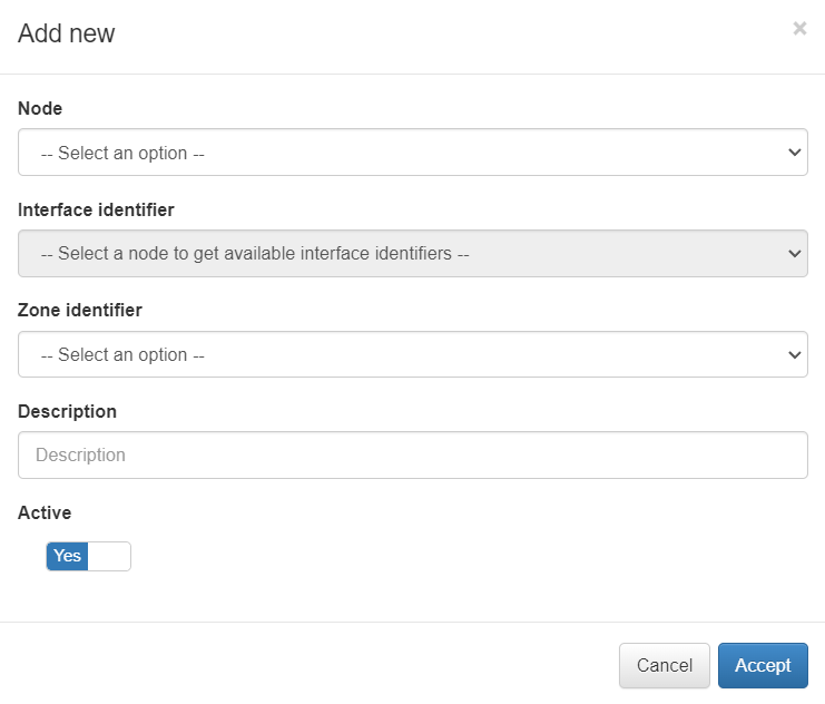
Node: Select the node for the new interface.
Interface identifier: Network interface with the main zone to associate.
Zone identifier: The zone that we want to associate to the interface.
Description: Descriptive comment.
Active: Flag to enable or disable the interface.
In this example we select the only existing network interface, the FWCorp zone and save by clicking on the Accept button.
4.7.1.5.5. VPNGW Hosts
Previously, we have assigned the “FWCorp” zone to the VPN Gateway network interface. The host identification (in terms of subnets and/or individual IP addresses) is used to distinguish server subzones from the FWCorp zone.
You can locate the Hosts management section by opening VPNGW > FARM (node that was previously created) > Hosts.
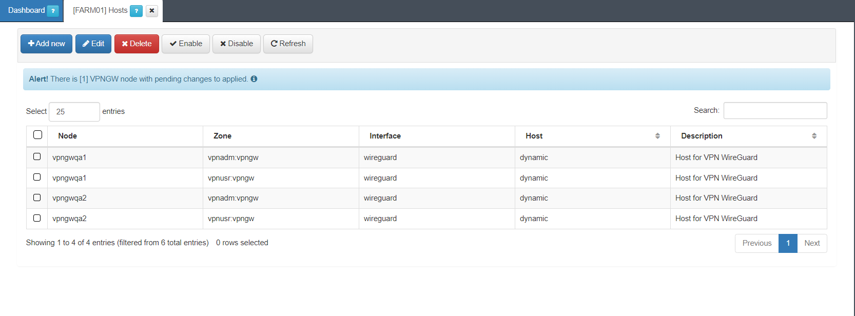
This view displays the Node, Zone, Interface, Host, and Description fields.
By clicking on the Add new button, it will display the following window:
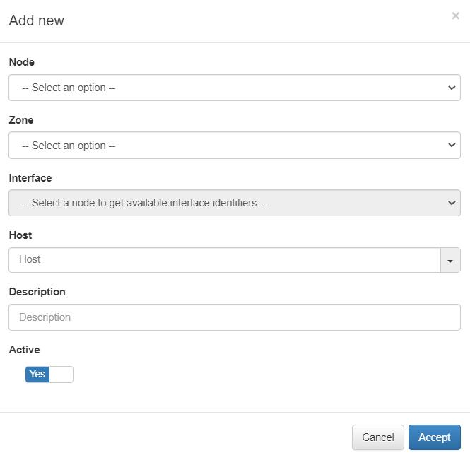
Node: Select the host node.
Zone: Select a zone for VPN.
Interface: Choose an interface according to the selected node.
Host: Select a host.
Description: Add a description to the host.
Active: Flag to enable or disable the host.
You can also edit, delete, enable, and disable policies using the correspondent buttons located at the top row of this view.
4.7.1.5.6. VPNGW Policies
Policies define the connections between previously defined zones in a high level. Initially, you need to create a policy that denies traffic between all defined zones. Later, you can open the traffic according to your convenience.
You can locate the policies management section by opening VPNGW > FARM (node that was previously created) > Policies.
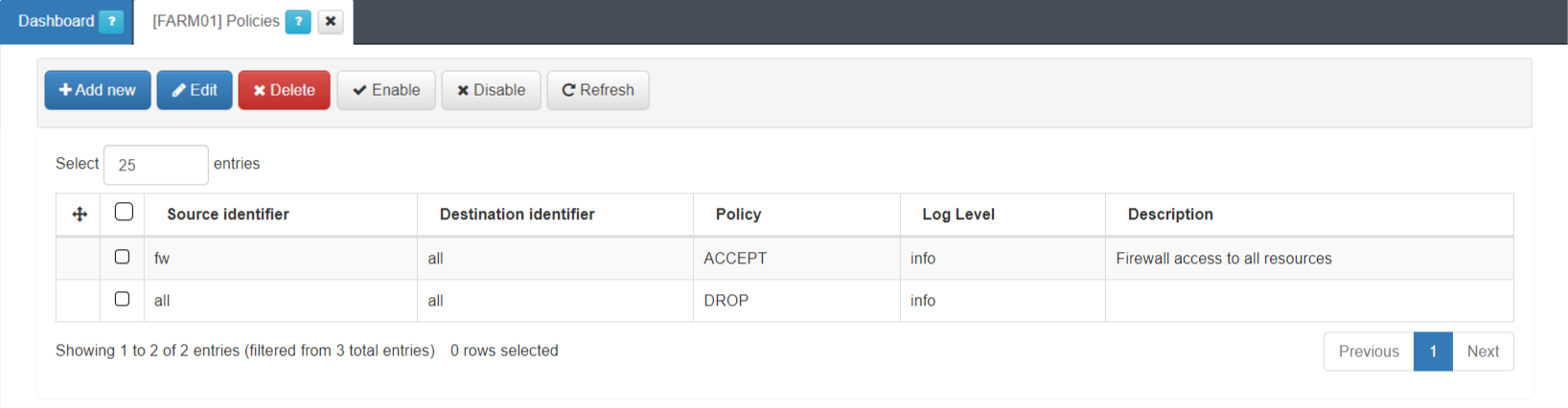
This view displays the Source identifier, Destination identifier, Policy, Log Level and description fields.
You can create a new policy by clicking on the Add new button. It will display the following configuration window:
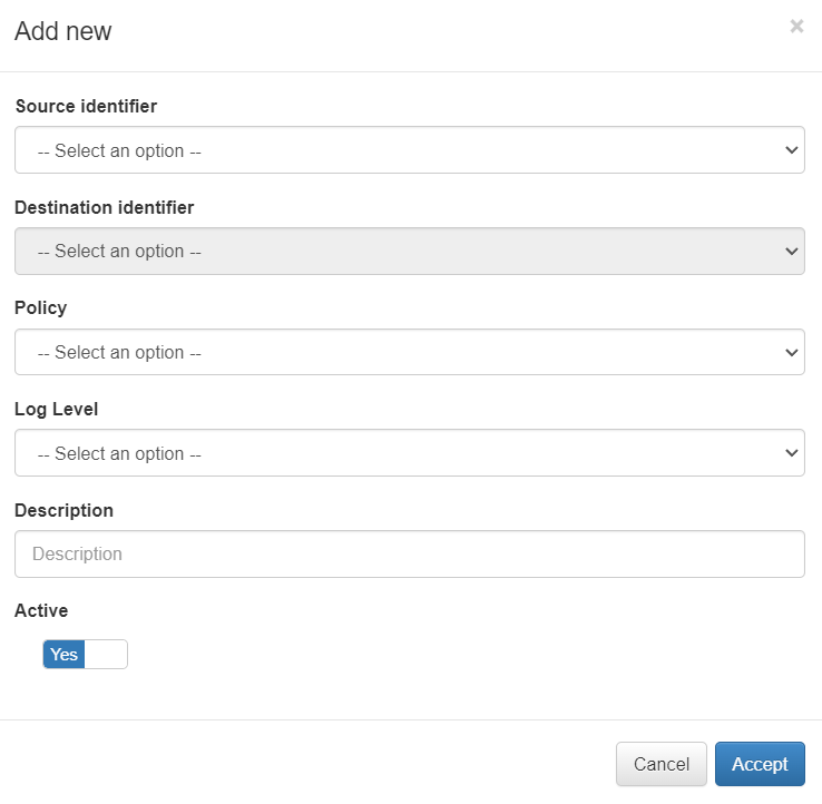
Source identifier: Zone from which the communication occurs.
Destination identifier: Zone to which the communication occurs.
Policy: Action we want to perform with the communication.
Log Level: Select the log level.
Description: Description of the policy
Active: Flag to enable or disable the interface.
In our example, we created a policy from all the zones to all the zones with the action of discarding (DROP) the communication.
You can also edit, delete, enable, and disable policies by using the correspondent buttons located at the top row of this view.
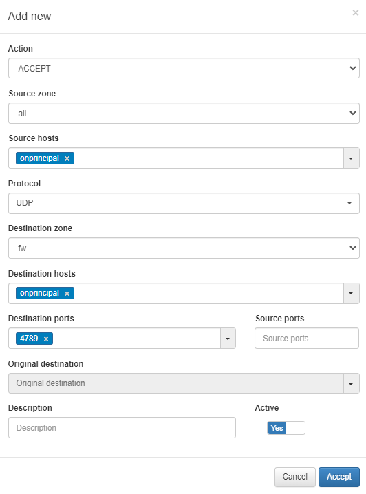
4.7.1.5.7. VPNGW Rule
To allow VPN traffic monitoring, you need to create a rule that accepts UDP port 4789 traffic from any zone to the firewall.
You can locate the rules management section by opening VPNGW > FARM (node that was previously created) > Rules.
Create a new rule by clicking on the Add new button, and use the parameters shown in the following image:
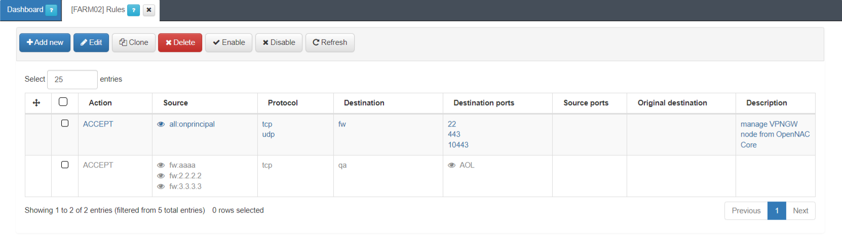
In the following image you can see other rules examples:
The next step will be to configure WireGuard or OpenVPN, depending on your network situation.
4.7.1.5.8. WireGuard
To configure WireGuard, you need to apply the Farm configuration and the Node configuration.
4.7.1.5.9. Farm configuration
The Farm configuration tab allows you to configure tunnel settings and Dynamic VPN zones.
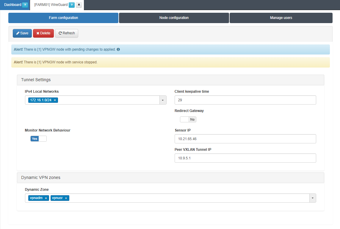
Tunnel Settings
IPv4 Local Networks: Local networks in CIDR IPv4 format that can be accessed through the VPN. When the connection is established, the client receives the connection routes, enabling it to know which networks are accessible. It refers to the IP range that will be configured in the WireGuard configuration file (AllowedIps). This range determines the set of IP addresses that clients connecting to the VPN can access.
Client keepalive time: How often a keepalive packet is sent to keep the connection active (in seconds). We recommend to use 25 seconds.
Redirect Gateway: Flag to enable Gateway redirection. Enabling it changes the the IPv4 Local Networks to 0.0.0.0/0.
Monitor Network Behavior: If enabled, the traffic that is passing through the VPN connection will be monitored. Enabling it, displays the following fields.
Sensor IP: : IP address for the ON Sensor BackEnd (the sensor external IP).
Peer VXLAN Tunnel IP: Remote IP address for the ON Sensor BackEnd inside the VXLAN tunnel for traffic monitoring. It is recommended to use the 192.168.70.1, but other IP addresses could also be used. Note that the Peer VXLAN Tunnel IP must match the IP address assigned to the sensor’s VXLAN-TAP interface.
Dynamic VPN zones
Dynamic zone: Zones that will be dynamically associated to the VPN access groups. They will be used in the access policies.
Warning
Remember to to click on the Save button to apply the configuration.
4.7.1.5.10. Node configuration
The Node configuration tab allows you to configure WireGuard nodes.
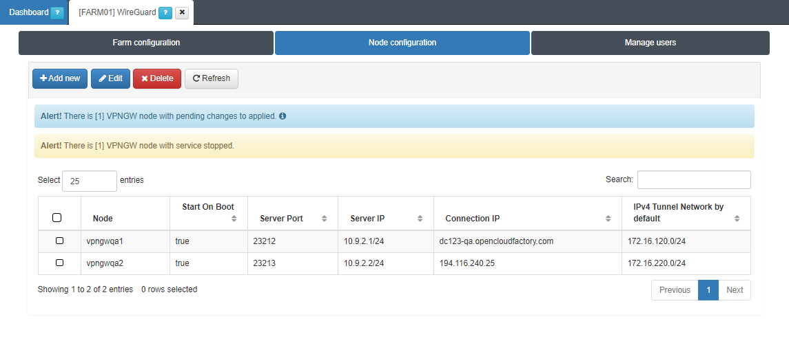
By clicking on the Add new button, it will display the following configuration window:
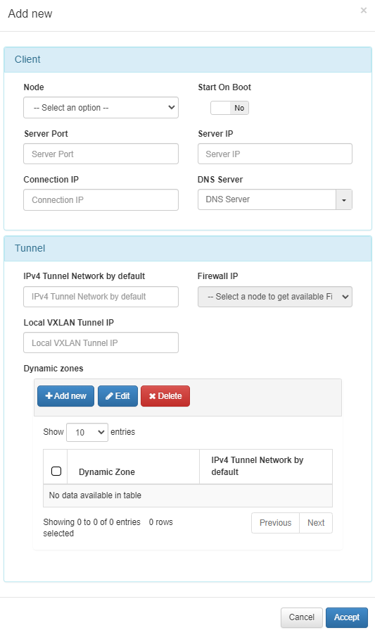
Client
Node: Select in which node you are going to apply the configuration.
Start On Boot: Enable this flag if you want the VPN Gateway to start when the machine reboots. If it is disabled, you have to manually start the VPN after rebooting.
Server Port: Port that is listening inside the Firewall to receive new connections.
Server IP: The IP to use on the WireGuard network interface on the VPN Gateway server. It is recommended to use the 192.168.71.1/24, but other IP addresses could also be used.
Connection IP: VPNGW node public IP (ON VPNGW node external IP).
DNS Server: DNS server IP.
Tunnel
IPv4 Tunnel Network by default: Network in IPv4 CIDR format for remote users. Pool of IP addresses to be offered from the VPN Gateway. This network must be unique in your organization.
Firewall IP: The IP that has communication with the sensor.
Local VXLAN Tunnel IP: This has to be an IP address from the network of the VXLAN-TAP interface of the sensor.
Dynamic zones: This subsection allows you to assigning an IPv4 Tunnel Network by default to a dynamic zone.
4.7.1.5.11. OpenVPN
To configure OpenVPN, you need to apply the Farm configuration and the Node configuration.
Configuring OpenVPN depends on the previous configuration of CMDB objects, Radius authentications, Certificate authorities, and Server certificates. For more information, see the VPNGW CMDB section.
This view displays two different tabs:
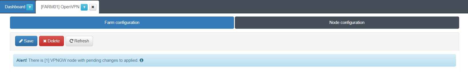
4.7.1.5.12. Farm configuration
The Farm configuration tab allows you to configure Backend Settings, Cryptographic Settings, Tunnel Settings, and Client Settings.
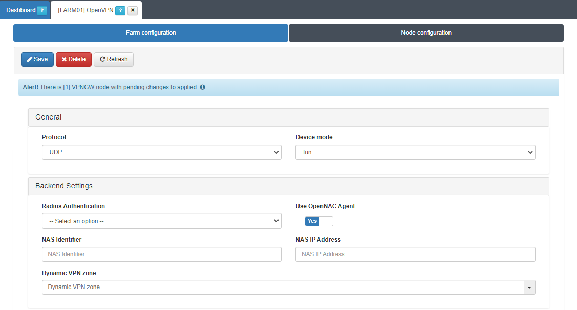
General
Protocol: Protocol to be used (UDP or TCP).
Device mode: Select the device mode (turn or tap).
Backend settings
Radius Authentication: Select the RADIUS authentication protocol (previously configured in the CMDB).
Use OpenNAC Agent: Flag to enable using the OpenNAC Agent.
NAS identifier: Desired identifier for this VPN Gateway. It will be the one that appears in the RADIUS logs.
NAS IP address: IP that is sent to the RADIUS. It was obtained when Configuring the Huntgroups file. See the 2SRA configuration section for more information.
Dynamic VPN zone: Zone that will be dynamically associated to the VPN access groups.
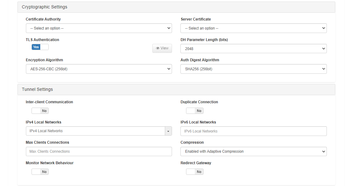
Cryptographic settings
Certificate Authority: Select a certificate authority (previously configured in the CMDB).
Server Certificate: Select a server certificate (previously configured in the CMDB).
TLS Authentication: Flag to enable TLS Authentication (enable it).
DH Parameter Length (bits): The number of bits that the DH prime must have. Recommended minimum 2048.
Encryption Algorithm: The encryption algorithm to be used. It’s recommended to use the AES-256-CBC algorithm.
Auth Digest Algorithm: The algorithm to use to make the hash. It’s recommended to use the SHA256 algorithm.
Tunnel Settings
Inter-client Communication: If enabled, all communication between connected users will only go through the VPN server. If it is disabled, the communication will reach the IP layer, which means it will be subject to firewall rules and could potentially be less secure.
Duplicate Connection: If enabled, multiple connections with the same user are allowed, so a certificate can be used by more than one connection/user. If disabled, each VPN certificate must have its own CN, so each connection/user has a unique certificate.
IPv4 Local Networks: Local networks in CIDR IPv4 format that can be accessed through the VPN. When the connection is established, the connection routes are sent to the client so that it knows these networks.
IPv6 Local Networks: Local networks in CIDR IPv6 format that can be accessed through the VPN. When the connection is established, the connection routes are sent to the client so that it knows these networks.
Max Clients Connections: Maximum number of users that can connect through the VPN.
Compression: Choose the type of compression to use. We recommend the “Enabled with Adaptive Compression” option.
Monitor Network Behaviour: If enabled, the traffic that passes through the VPN connection will be monitored.
Redirect Gateway: If enabled, all traffic, including internet traffic, is redirected via VPN. In this case, it is necessary to configure the DNS so that the resolution is internal. If disabled, only local networks can be accessed through the VPN.
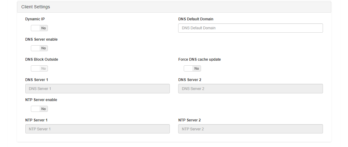
Client Settings
Dynamic IP: Enabling this flag allows the VPN to assign IPs dynamically.
DNS Default Domain: Defaulf domain name.
DNS Server enable: Flag to enable the configuration of the DNS servers.
DNS Block Outside: Flag to enable DNS blocking outside.
Force DNS cache update: Flag to force clearing the client’s DNS server cache.
DNS Server 1: Fill in if you want to use a specific DNS server.
DNS Server 2: Fill in if you want to use another specific DNS server.
NTP Server enable: Enable the configuration of the NTP servers.
NTP Server 1: Fill in if you want to use a specific NTP server.
NTP Server 2: Fill in if you want to use another NTP server.
4.7.1.5.13. Node configuration
The Node configuration tab allows you to configure OpenVPN nodes.
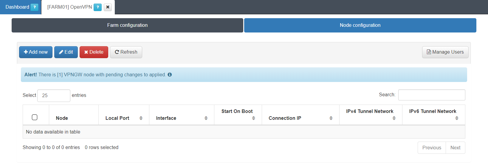
By clicking on the Add new button, it will display the following configuration window:
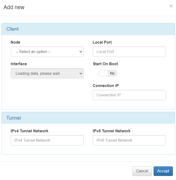
Client
Node: Select the client node.
Local Port: Select a local port to the node.
Interface: Select an interface.
Start on Boot: Enable if you want that the VPN Gateway starts when rebooting the machine. If it is disabled, you have to manually turn on the VPN after reboot.
Connection IP: Connection IP or domain.
Tunnel
IPv4 Tunnel Network: Network in IPv4 format where the tunnel will be deployed. This network must be unique in your organization.
IPv6 Tunnel Network: Network in IPv6 CIDR where the tunnel will be deployed. This network must be unique in your organization.
4.7.1.5.14. Apply firewall configurations
Once you have finished all the previous configurations, you will be able to Start the WireGuard or OpenVPN services.
Open the VPNGW > Manage VPNGW section located on the main menu. Select the configured node, click on the correspondent service, in our example we will use the Manage WireGuard button, and select Deploy & restart. A pop-up window will be displayed reporting on the status of the various processes that will execute before starting the WireGuard service. It will also report any warnings or errors.
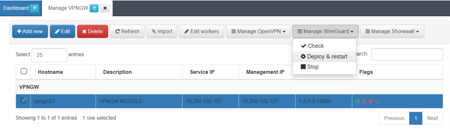
Initially the three flags displayed in this view will be in red.
The first one, the flame, refers to the Shorewall service.
The second one, the first star, refers to WireGuard.
The last star, refers to OpenVPN.
If the deployment and restart of the services was OK, they will change their status to green.