4.7.2.10. Portal Configuration
This section is dedicated to configuring the necessary flows for the 2SRA use case in the Administration Portal. It involves setting up and starting the VPN service, creating various VPN user validation policies, and establishing different authorities for the authorization process.
We will proceed by navigating through different menus in the Administration Portal, starting with the VPN menu and then moving on to the General menu.
4.7.2.10.1. Populating the VPN Data Section
To populate the VPN data section, go to Configure > VPN > VPN data > Objects.
This view presents a window containing numerous preconfigured objects, mostly protocols. You can create and manage these objects from this section.
To create a new VPN object, click on the Create new button. It will display a window with the following configuration fields:
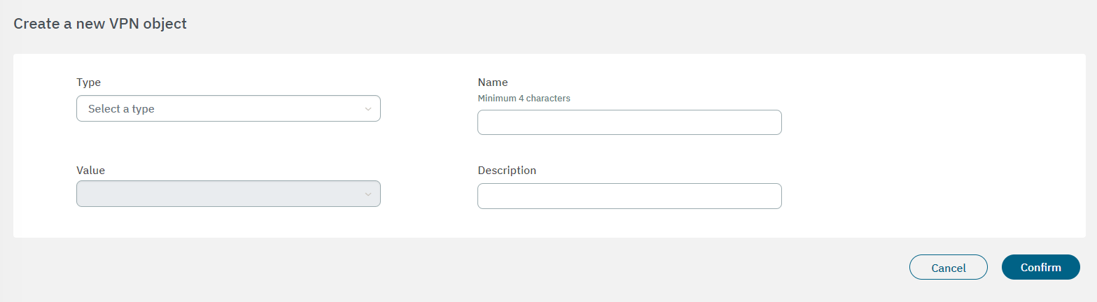
Type:Object type:
Network: One network. Ex: 172.16.1.0/24
Host: One concrete host. Ex: 172.16.1.13
Protocol: One protocol. Ex: tcp: 443
Name: Object identifier name. It should have at least 4 characters.
Value: Enter a list of more than one protocol or [tcp|udp]:[port number] or icmp:[type-name|type|type/code].
Description: Here you can add a description of the object.
After adding values to the the fields, click on Confirm to save the configurations.
4.7.2.10.2. Creating Farms and Nodes
To configure nodes, first you must crete a “farm” where those nodes will be associated to. A “farm” refers to a group of interconnected servers that work together to provide High Availability. Each server within the farm is known as a node, and they collectively form a robust and fault-tolerant infrastructure.
So before creating nodes, let’s create a farm that will centralize the configuration of all nodes associated to it.
See the Manage VPN farms section for more information about farms.
4.7.2.10.2.1. Creating a new farm
To create a new farm, click on the Create new button. It will display the following window:
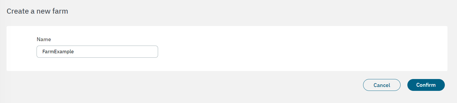
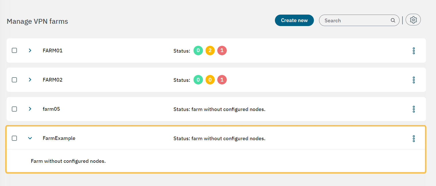
Give a name to the new farm and click on Confirm. It will display the message “A new row has been added” and you will see your new farm displayed in the main view.
4.7.2.10.2.1.1. Configuring workers
After creating the farm, you have to add nodes to it. If you want workers to be available in the moment you are creating your nodes, you can do it beforehand.

Click on the engine icon to open the “manage VPN workers” window:
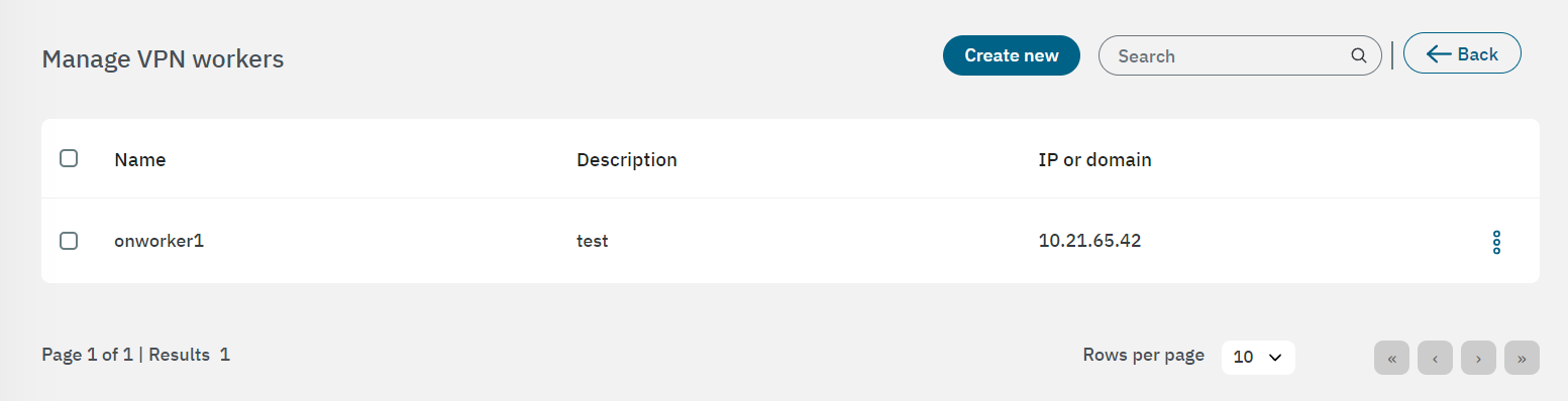
Click on Create new to create a new worker. Enter the information requested in the following fields:
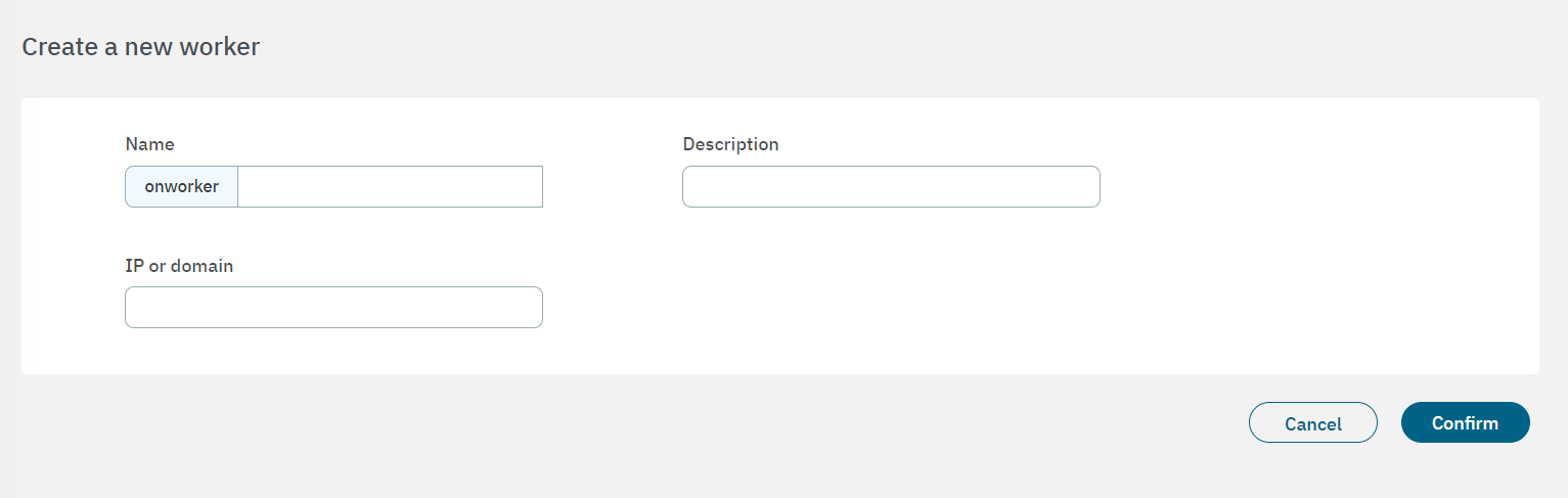
Name: The onworker identification name.
Description:You can enter a worker description.
IP or domain: The worker’s IP or domain.
Click on Confirm to save your configurations and you will see the worker displayed in the Manage VPN workers table.
4.7.2.10.2.1.2. Adding nodes to a farm
Back to the main view, after having created a farm and configured a worker, it is time to add nodes to the farm.
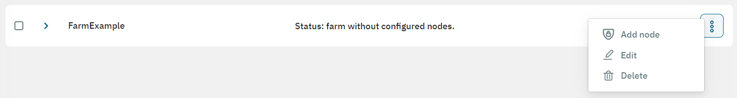
The three-dot icon at the end of the farm row displays the Add node option. Select it to open the following window where you can configure the node:
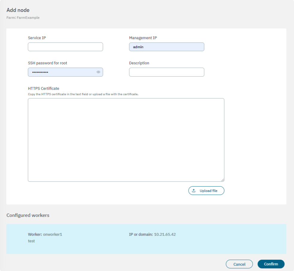
Service IP: IP assigned to the node to be imported.
Management IP: Field for the management IP of the node.
SSH password for root: SSH credentials of the node, by default root/opennac.
Description: Description of the node.
HTTPS Certificate: Copy the HTTPS certificate in the text field or upload a file with the certificate by clicking on the Upload file button.
If you don’t have a certificate you can create it with the following commands:
mkdir certificates
cd certificates/
openssl genrsa -out mydomain.key 2048
openssl req -new -key mydomain.key -out mydomain.csr
openssl x509 -req -days 365 -in mydomain.csr -signkey mydomain.key -out mydomain.crt
bash -c 'cat mydomain.key mydomain.crt' >> mydomain.pem
cat mydomain.pem
Copy the content of mydomain.pem to the HTTPS Certificate field. This file also includes the RSA Private Key in the certificate.
You will see the configured workers available at the bottom of this view.
Click on Confirm to save the configurations.
In the following topics we will detail how to configure zones, interfaces, policies, rules and hosts.
4.7.2.10.3. Configuring Zones
You can locate the Zones section by going to Configure > VPN > Farm > Zones. Under a specific farm, you will have the option to access and configure the zones associated with it.
To ensure communication between the frontend and the zones of standard and critical servers, the traffic passes through the Corporate Firewall. As a result, these zones will be considered subzones of the previous zone. To achieve this configuration, you need to create these zones and subzones within the zone configuration section.
The firewall (fw) zone itself is already created by default.
You can create the rest of zones you need by clicking on the Create new button. It will display the following configuration window:
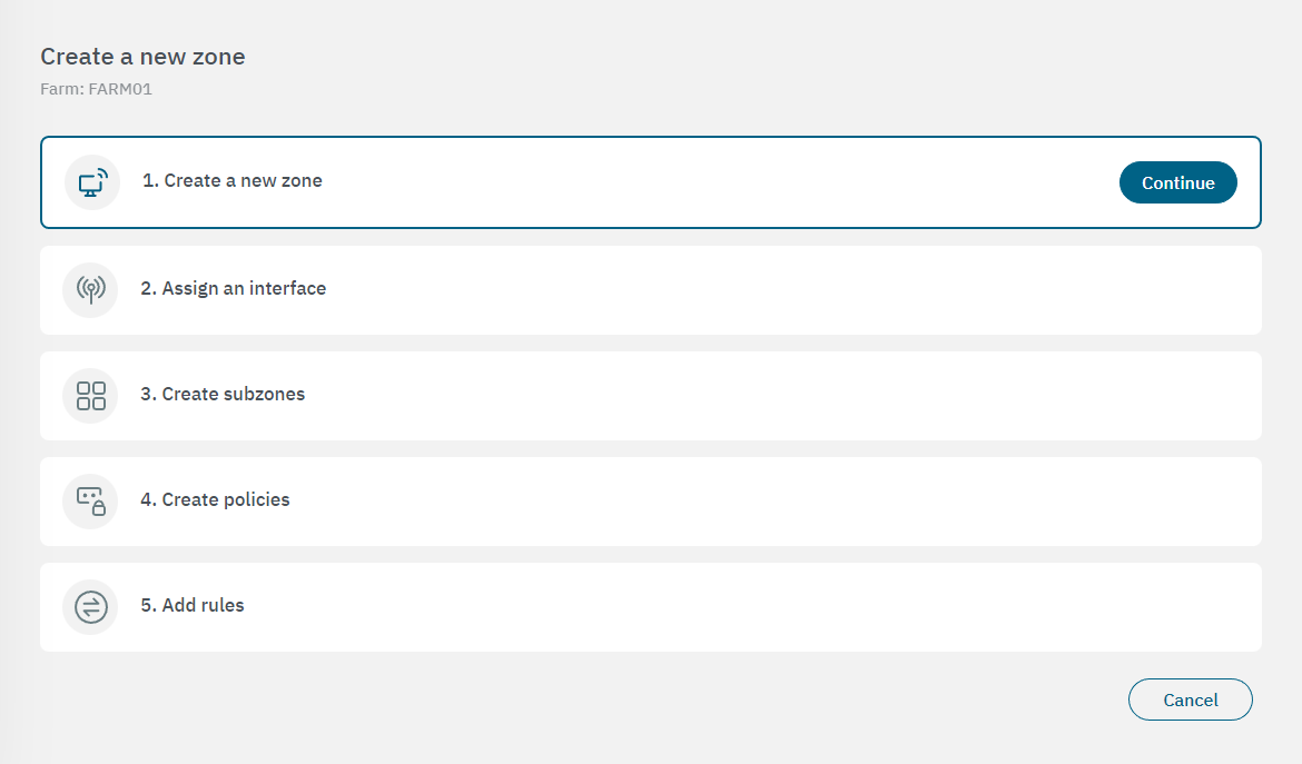
Click on Continue to open the first properties configuration window. After configuring each property, click on “Continue” again to proceed to the next configuration window.
4.7.2.10.3.1. Create a new zone
In the following image you can see the fields displayed in the “Create a new zone” property:
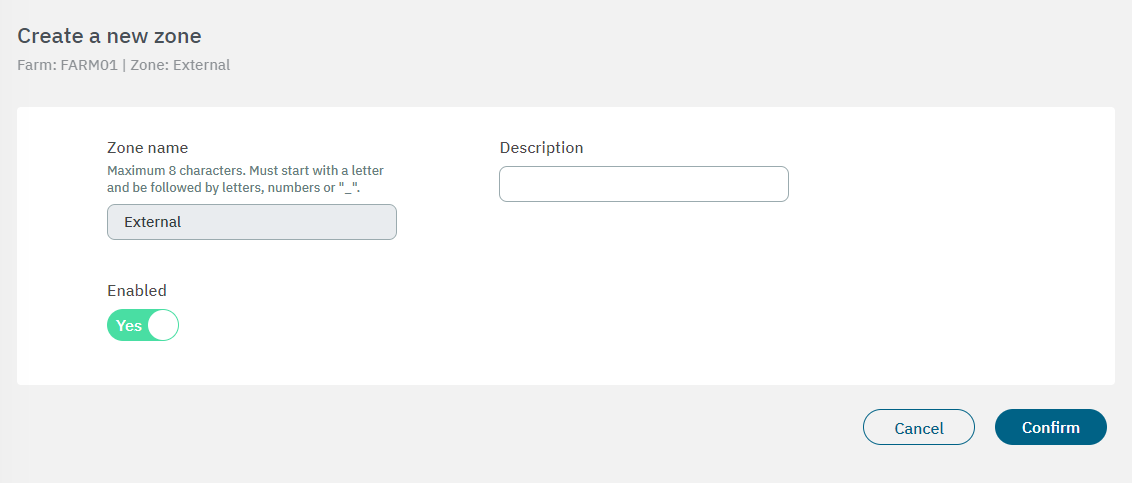
Name: The zone identification name must start with a letter followed by alphanumerical characters or underscore. It must have a maximum of 8 characters. - Example: “FWCorp”
Description: Here you can add a Zone description.
Enabled: Flag to enable or disable the zone.
After finishing the configuration, click on Confirm. It will lead you to the first configuration window.
4.7.2.10.3.2. Assign an interface
In the following image you can see the fields displayed in the “Assign an interface” property:
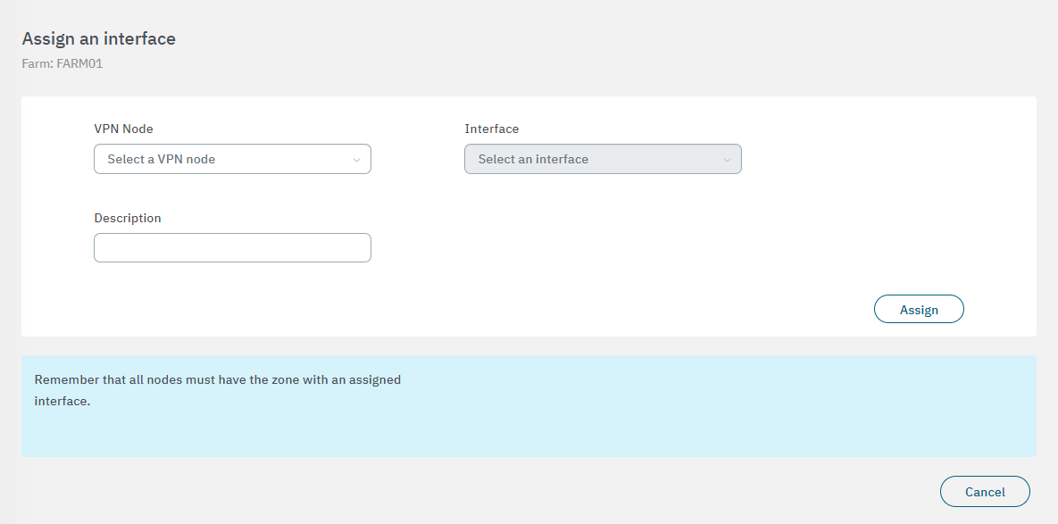
VPN Node: Select the node for the interface.
Interface: Select the network interface to associate with.
Description: You can add descriptive comment.
After finishing the configuration, click on Confirm. It will lead you to the first configuration window.
4.7.2.10.3.3. Create subzones
You can skip this step if you don’t want to create subzones. In the following image you can see the fields displayed in the “Create subzones” property:
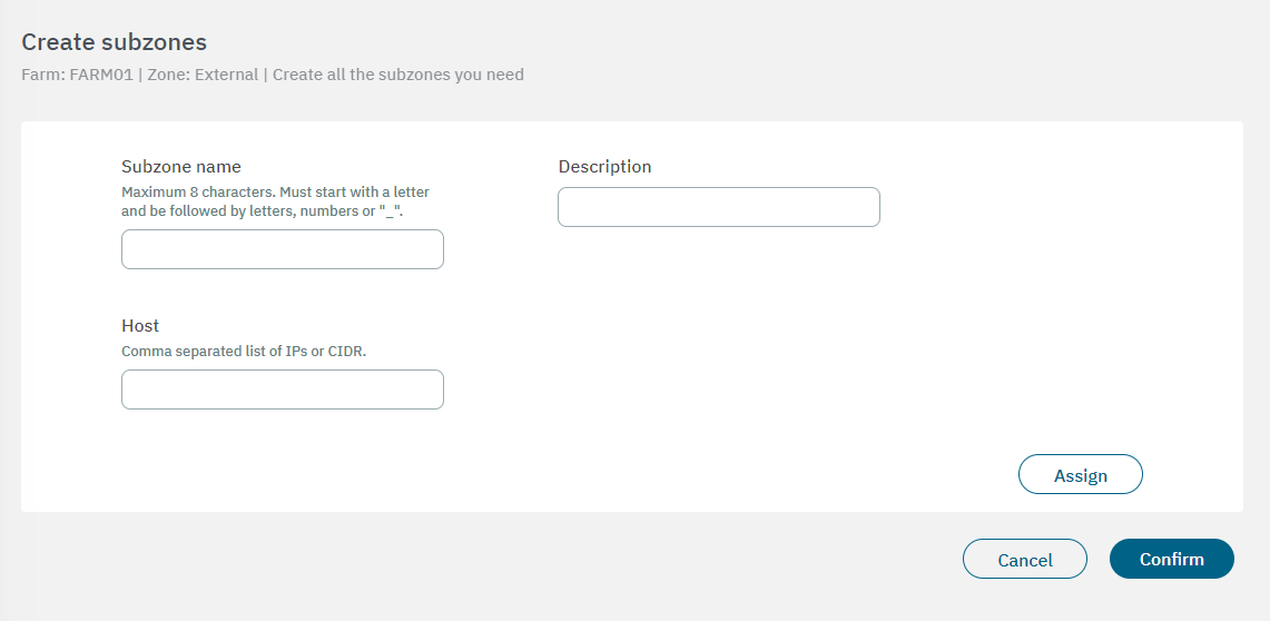
Subzone name: The subzone identification name must have a maximum of 8 characters, start with a letter and be followed by letters, numbers or “_”.
Description: You can add descriptive comment
Host: Comma separated list of IPs or CIDR.
After finishing the configuration, click on Confirm. It will lead you to the first configuration window.
4.7.2.10.3.4. Create policies
You can skip this step if you don’t want to create policies for this specific zone. From this configuration step, in addition to creating a new policy, you can directly assign it to the zone you are creating. In the following image you can see the fields displayed in the “Create policies” property:
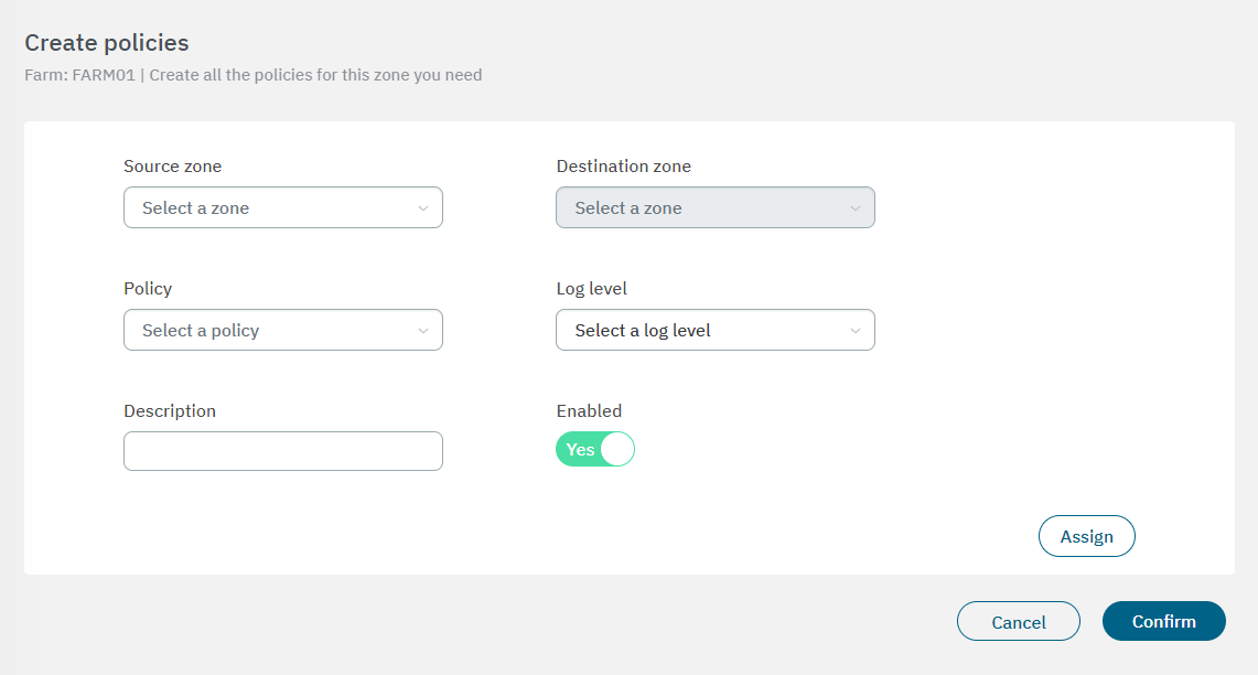
Source zone: Zone from which the communication occurs.
Destination zone: Zone to which the communication occurs.
Policy: Action we want to perform with the communication.
Log Level: Select the log level.
Description: Description of the policy.
Enabled: Flag to enable or disable the policy.
After finishing the configuration, click on Confirm. It will lead you to the first configuration window.
4.7.2.10.3.5. Add rules
You can skip this step if you don’t want to create rules for this specific zone. In the following image you can see the fields displayed in the “Addd rules” property:
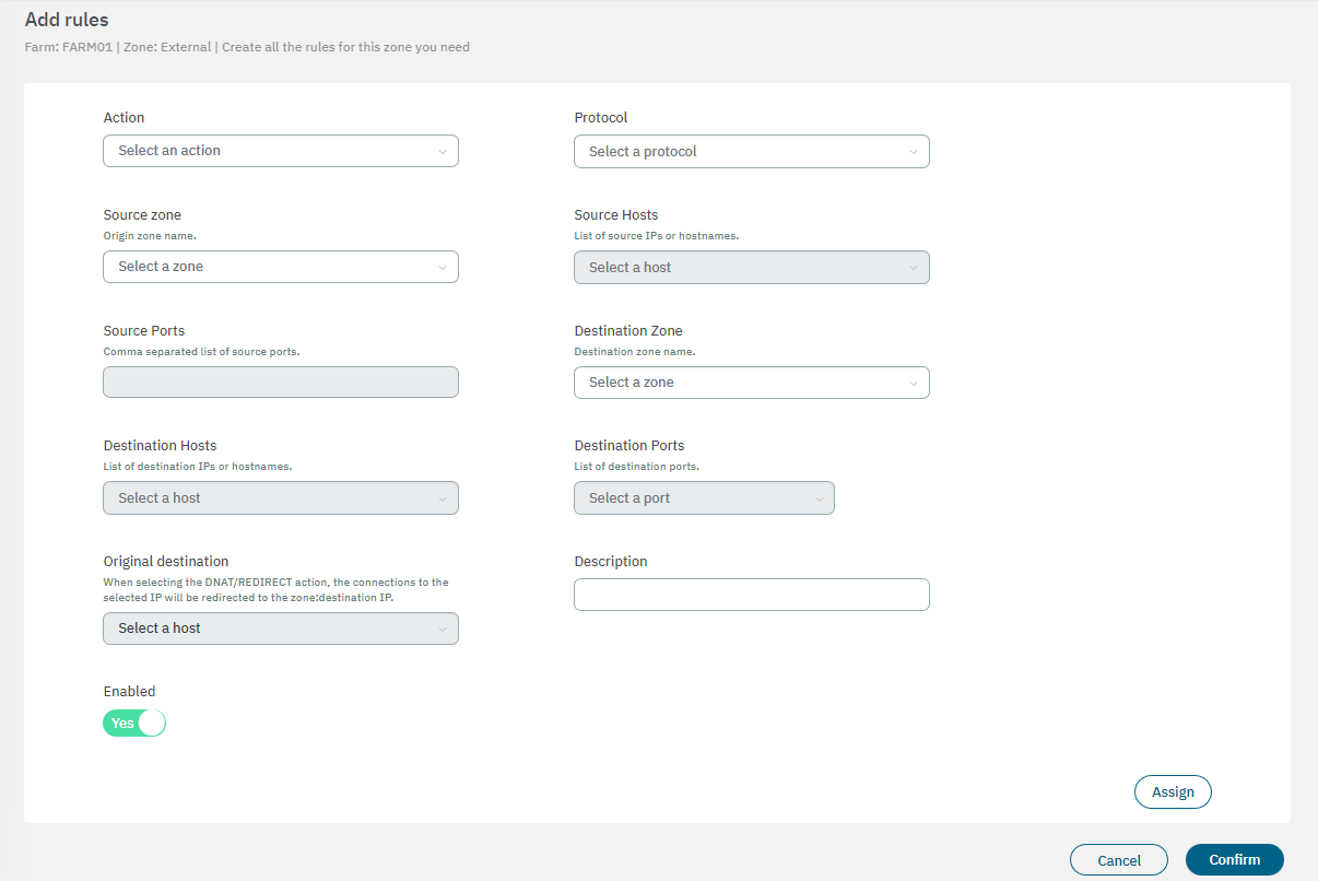
Action: Select the instruction of the rule (ACCEPT, DNAT, DROP, LOG & ACCEPT, LOG & REJECT, REDIRECT, REJECT).
Protocol: Select the rule protocol (All, TCP, UDP, ICMP, ESP)
Source zone: Origin zone name.
Source hosts: Select it from a list of source IPs or hostnames.
Source ports: Comma-separated list of source ports.
Destination zone: Destination zone name.
Destination hosts: Select a destination host to the rule.
Destination ports: Select a destination port to the rule.
Original destination: When selecting the DNAT/REDIRECT action, the connections to the selected IP will be redirected to the zone:destination IP.
Description: Add a description to the rule.
Enabled: Flag to enable or disable the rule.
After finishing the configuration, click on Confirm to finally create a new zone.
4.7.2.10.4. Configuring WireGuard
The VPN WireGuard configuration has its own section under the farm menu.
Go to Configure > VPN > Farm > Wireguard to edit the Farm configuration and Node Configuration properties:
The Farm configuration properties allows you to configure tunnel settings and Dynamic VPN zones for the Wireguard service. This configuration will synchronize with all nodes under this farm.
Enable the flag Enable WireGuard on the farm to see the following configuration options available:
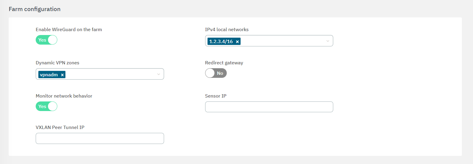
Enable Wireguard on the farm: Flag to enable the service.
IPv4 Local Networks: Local networks in CIDR IPv4 format that can be accessed through the VPN. When the connection is established, the client receives the connection routes, enabling it to know which networks are accessible. It refers to the IP range that will be configured in the WireGuard configuration file (AllowedIps). This range determines the set of IP addresses that clients connecting to the VPN can access.
Dynamic VPN zone: Zones that will be dynamically associated to the VPN access groups. They will be used in the access policies.
Redirect gateway: Flag to enable Gateway redirection. Enabling it changes the the IPv4 Local Networks to 0.0.0.0/0.
- Monitor Network Behavior: If enabled, the traffic that is passing through the VPN connection will be monitored. Enabling it displays the following fields:
Sensor IP: : IP address for the ON Sensor BackEnd (the sensor external IP).
Peer VXLAN Tunnel IP: Remote IP address for the ON Sensor BackEnd inside the VXLAN tunnel for traffic monitoring. It is recommended to use the 192.168.70.1, but other IP addresses could also be used. Note that the Peer VXLAN Tunnel IP must match the IP address assigned to the sensor’s VXLAN-TAP interface.
4.7.2.10.5. Node configuration
The Node configuration properties allows you to apply configurations to a specific node instead of using its farm configuration.
By clicking on the icons highlighted in the following image, all fields become editable.
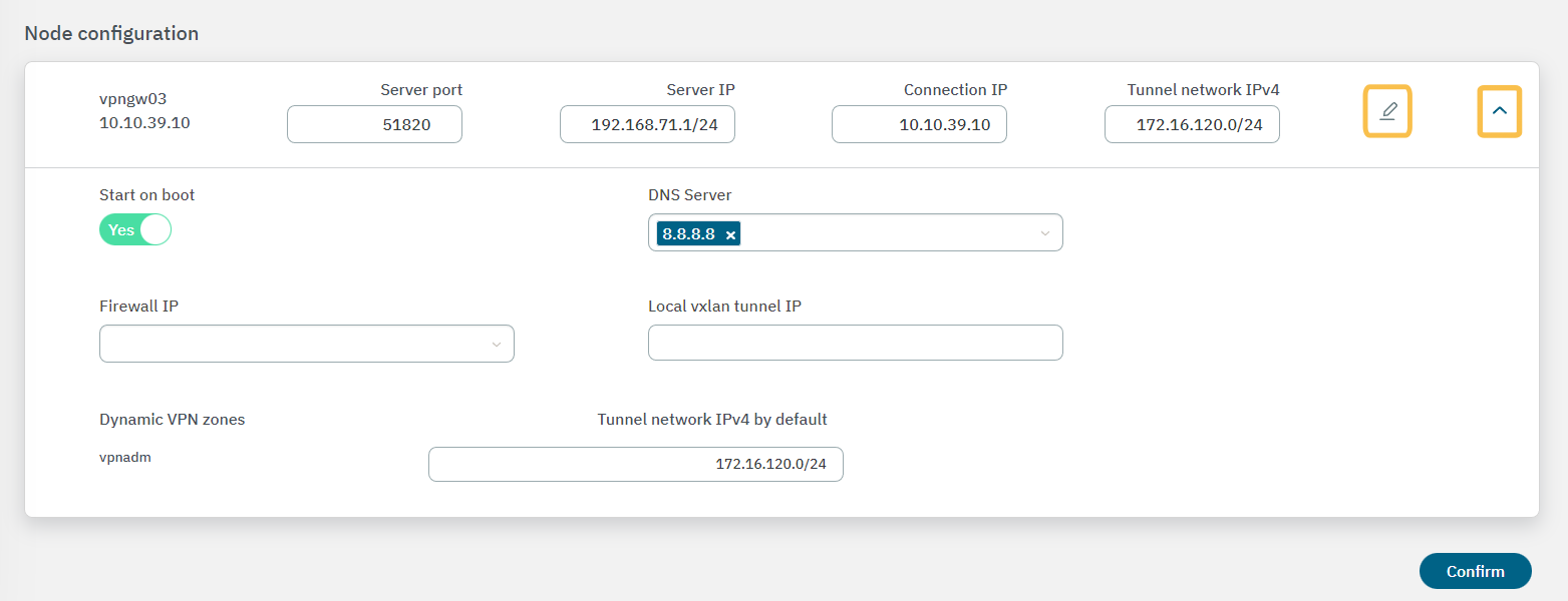
Server Port: Port that is listening inside the Firewall to receive new connections.
Server IP: The IP to use on the WireGuard network interface on the VPN Gateway server. It is recommended to use the 192.168.71.1/24, but other IP addresses could also be used.
Connection IP: VPNGW node public IP (ON VPNGW node external IP).
Start On Boot: Enable this flag if you want the VPN Gateway to start when the machine reboots. If it is disabled, you have to manually start the VPN after rebooting.
DNS Server: DNS server IP.
Firewall IP: The IP that has communication with the sensor.
Local VXLAN Tunnel IP: This has to be an IP address from the network of the VXLAN-TAP interface of the sensor.
Tunnel network IPv4 by default: Network in IPv4 CIDR format for remote users. Pool of IP addresses to be offered from the VPN Gateway. This network must be unique in your organization.
To understand the configuration of the Sensor interface, refer to the ON Sensor Node configuration for the 2SRA use case.
Once you have finished, click on Confirm to save your configurations.
4.7.2.10.5.1. Starting the WireGuard Service
Once you have finished all the previous configurations, the service will be ready for deployment so you can start the WireGuard service.
In the Configure > VPN > Manage VPN farms section, choose the configured farm where you want to start the service. At the end of the farm row, click on the three-dot icon to displays the following options:
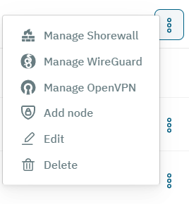
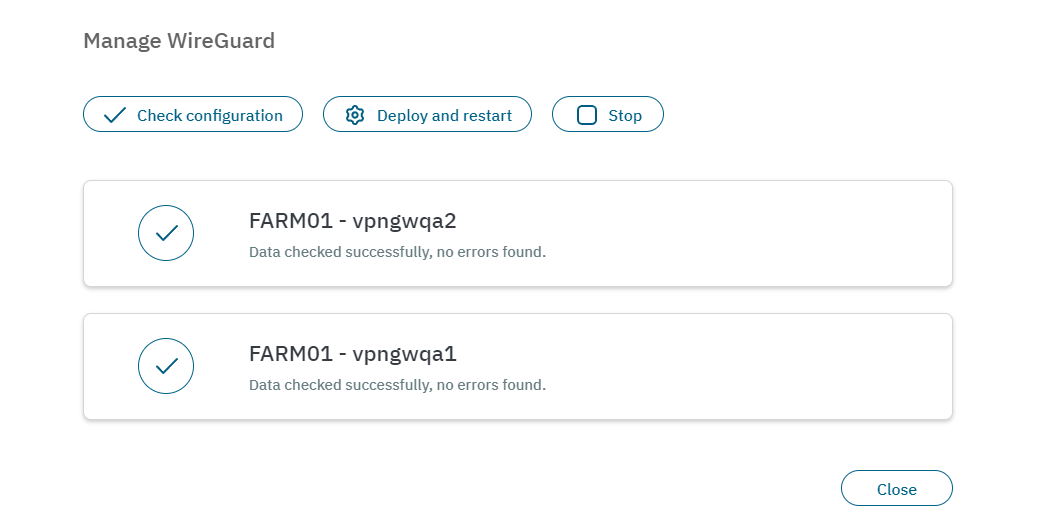
The Manage Shorewall, Manage Wireguard, and Manage OpenVPN options display the same window. It allows you to Check configuration, Deploy and restart, or Stop a service.
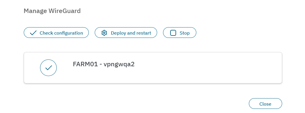
By clicking on Check configuration, a pop-up window will be displayed reporting on the status of the service. It will also report any warnings or errors.
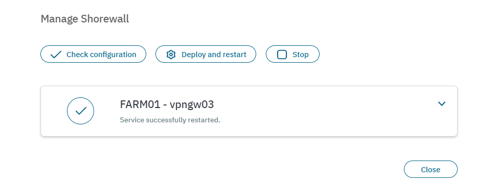
By clicking on Deploy and restart, It will indicate the status of the service. In the example below, the result is Service successfully restarted. If Any errors occur, it would report warnings and the status of the error.
See the Configure > VPN section in the Administration Portal for detailed information about the VPN module.
4.7.2.10.6. Agent VPN configurations
Agent Profiles
Agent Profiles contain settings that are sent to the Agents installed on client devices. The Agents gather information from the devices and then receive the Agent Profiles to apply the specified settings.
It is necessary to include the connection profile in the default Agent configuration profile that we have registered. By adding the connection profile to the default configuration, when the agent establishes a connection with the backend system, it will be able to receive and apply the VPN configuration.
Go to the Configure > General > Agent > Profiles section:
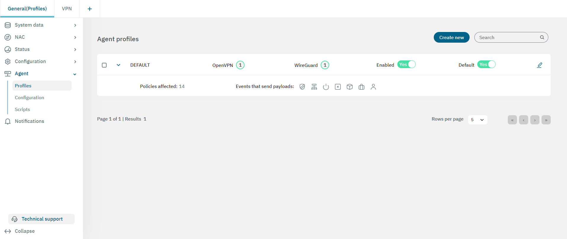
Click on the Edit button of the DEFAULT profile.
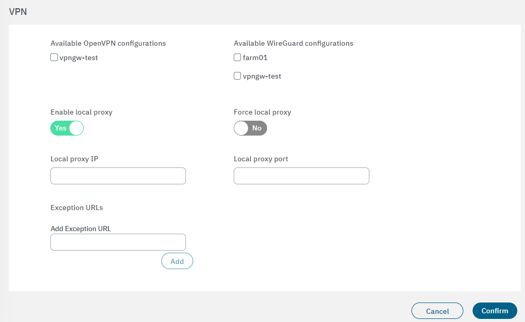
In the 2. Service configuration section, scroll down and find the VPN configuration.
You will find the Available OpenVPN/Wireguard configuration fields that allows you to select the VPN farm with the previously created settings.
Click on Confirm to save the changes.
In the 5. UI configuration section, enable all the flags available in this view. Enable OpenVPN or Wireguard according to the VPN service you are using.
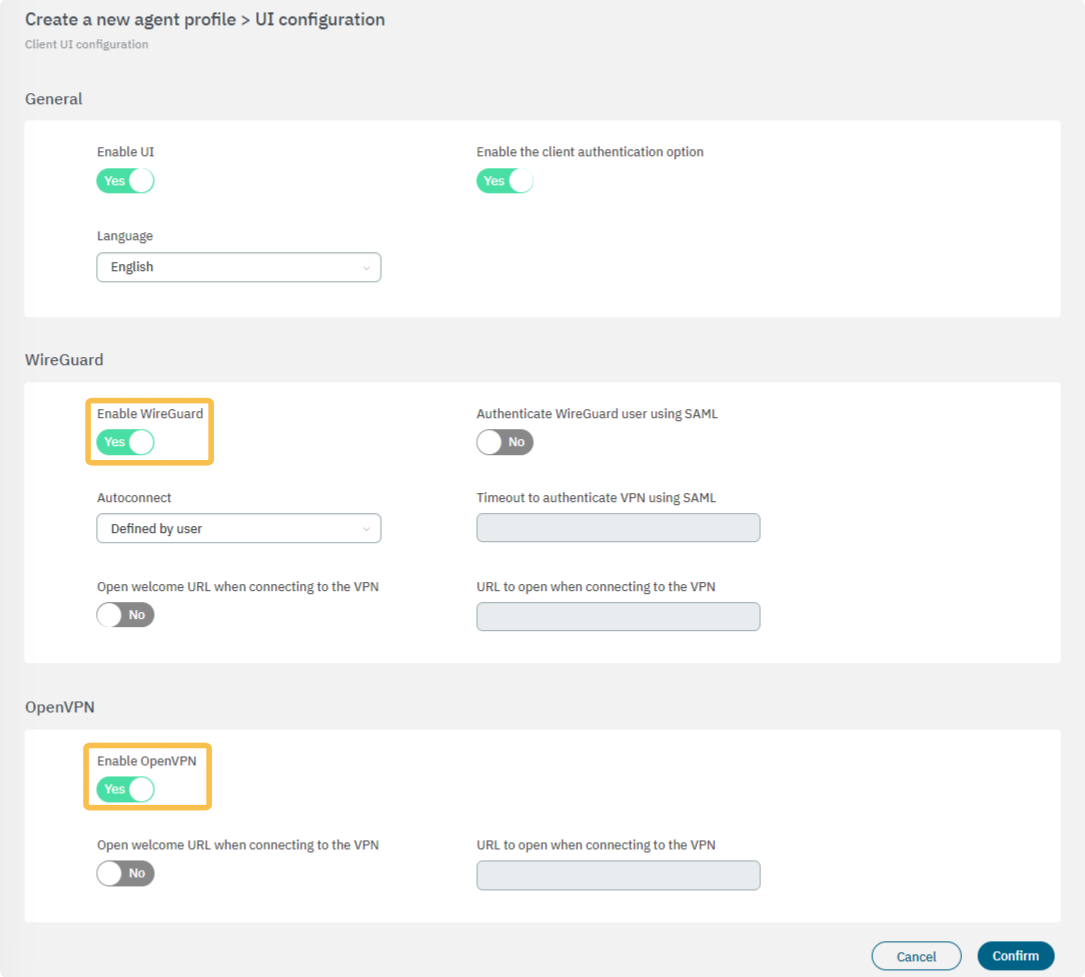
Click on Confirm to save the changes.
Agent download
After configuring the Agent profiles, we will configure the Agent download to indicate the connection IP and enable the use of VPNs such as WireGuard or OpenVPN.
Go to Configure > Agent > Configuration.
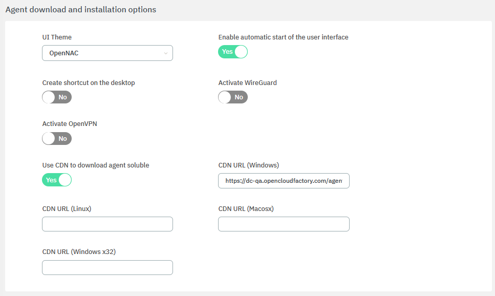
Scroll down to the Agent download and installation options configuration.
Enter the IP or name of the server, and enable Wireguard or OpenVPN according to what you have previously configured.
Note
In the IP or name of the server field, you should enter the Public URL of the VPN connection, which should be associated with the name registered in the public DNS and the certificate that was generated beforehand.
Click on Save to save the changes.
4.7.2.10.6.1. Wireguard VPN using SAML
The use of SAML to authenticate the VPN connections of the WireGuard service requires an additional configuration. To enable the SAML functionality in the ON Agent application, execute the following steps.
Go to Configure > General > Agent > Profiles
In the profile used for it (DEFAULT), click on the Edit option.
Edit the 5. UI configuration configuration and scroll down to the WireGuard section.
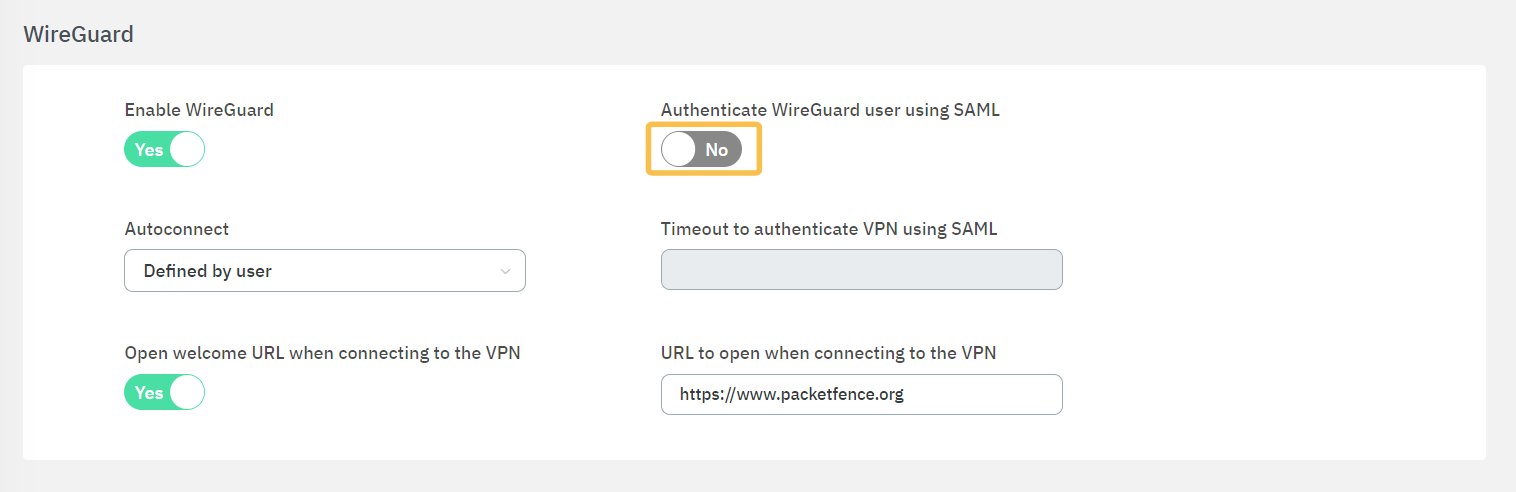
Enable the Authenticate WireGuard user using SAML flag.
4.7.2.10.7. Plugin Configuration (WireGuard only)
If you are using a WireGuard VPN service, it is necessary to configure its corresponding plugin. For OpenVPN this step is not necessary.
Go to the Configure > General > Configuration > Policy plugins section.
Scroll down to the 2SRA (VPN) plugins.
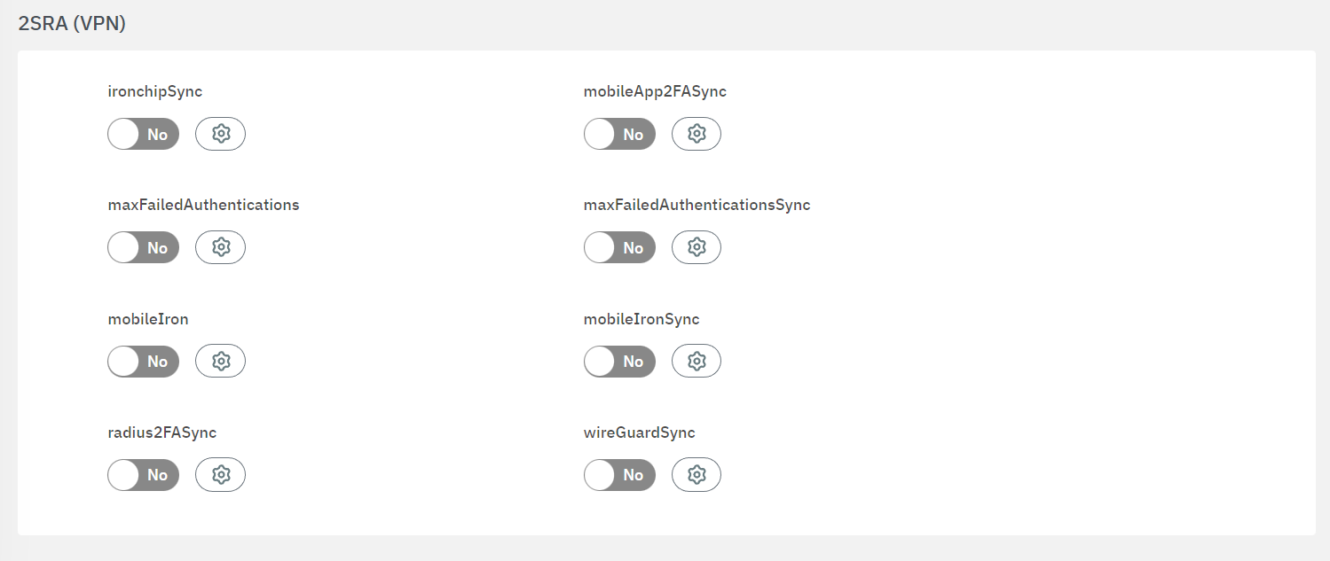
Click on the gear icon to open its configuration window.
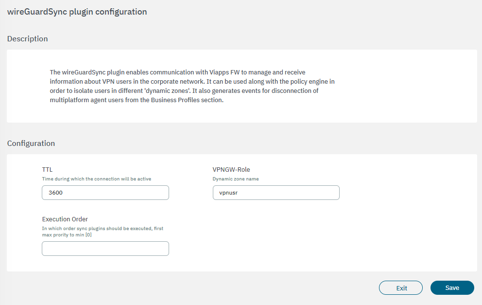
Enter the values for TTL, VPNGW-Role and Execution order and then click on the Save button.
4.7.2.10.8. Creating User Data Sources
By defining multiple User Data Sources (UDS) on a system, different authorities can be used in the authorization process. Active Directory attributes support this process.
To create a new UDS, follow the steps provided below:
Go to Configure > General > System data > User data sources
Click on the Create new button.
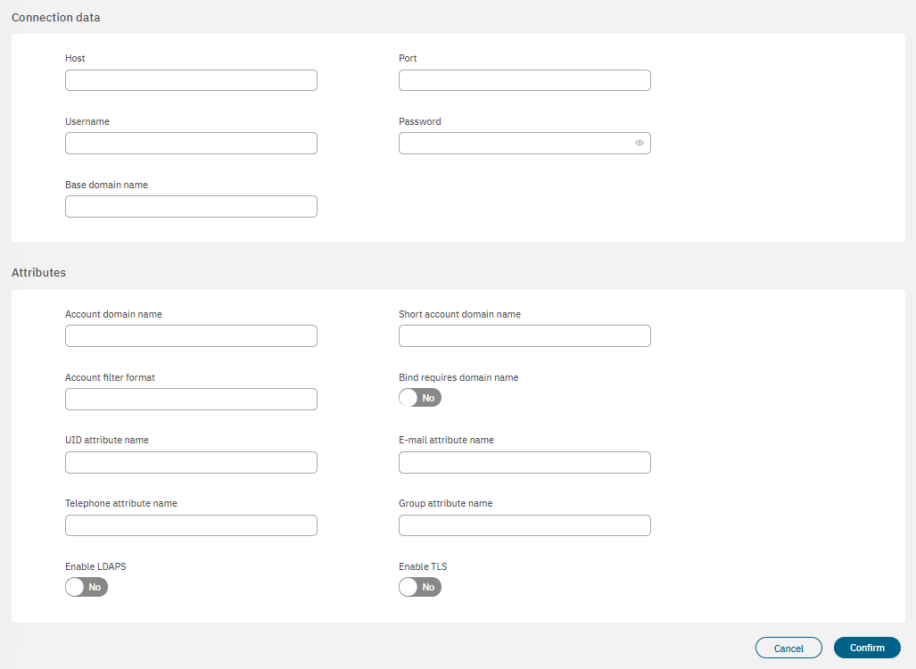
Define a name and select a type for the new UDS. In our example we will select the Active Directory type. It displays the following configuration properties:
Name: The name used by the UDS. In this case, this is a UDS type LDAP/AD, and for this reason, for instance: AD Mycompany.
Type: Defined as LDAP. The database connection could be used to get user attributes.
Enabled: The UDS can be enabled or disabled.
Read only: If the query is launched with a Read only flag. This will avoid any write action in the commands.
Host: The LDAP/AD IP where the queries are launched. For instance: 172.16.11.5, additional IPs can be added.
Port: The port used for the AD/LDAP Search query, by default, uses an unsecured connection. The default is 389 and if AD/LDAP SSL is enabled is 636.
Username: The user registered in the AD/LDAP server. This allows us to bind and use AD/LDAP information.
Password: The password for the AD/LDAP binding.
Base domain name: BaseDN at the top of the domain name structure. Our domain is named mycompay.local and its BaseDN is DC=mycompany,DC=local.
Account domain name: The DNS name for the domain is in uppercase. In this case MYCOMPANY.LOCAL.
Short account domain name: The short name for the domain or commonly named NETBIOS name. For instance, MYCOMPANY.
Account filter format: The attribute used to select users. We have included two options, but only one must be used. In this example sAMAccountName=%s is defined for Active Directory, and uid=%s for LDAP Servers.
Bind requires domain name: It is basically the credential you are using to authenticate against an LDAP. When using a bindDN, it usually comes with a password associated with it. Sometimes, anonymous binding doesn’t allow certain types of actions.
UID attribute name: The attribute is used to identify users’ IDs. The filter changes depending on if AD or LDAP is used.
E-mail attribute name: The filter is used to identify the email as an attribute of the user.
Telephone attribute name: The filter is used to identify the phone number as an attribute of the user.
Group attribute name: The filter use to identify the groups as an attribute of the user.
Enable LDAPS: For authenticating and authorizing users where LDAP communication is transmitted over an SSL tunnel port 636 TCP.
Enable TLS: For securing communication between LDAP clients and LDAP servers.
Once finished with this configuration window, click on Confirm. It should now be displayed in the User data sources table.
Check the Last status column, if it shows Ready, the configuration is done. If not, click on the three-dot icon located at the end of the row. It can display the following options:
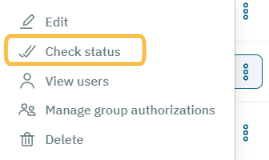
Select the Check status option, and if there are no errors, the UDS will change its state to Ready.
4.7.2.10.9. Creating LDAP filters
This section will guide you through the process of creating LDAP filters. These filters play a crucial role in segmenting groups of users who access the VPN and associating them with the dynamic zones in the VPN Gateway. By utilizing LDAP filters, you can assign different access ACLs (Access Control Lists) through the VPN.
Note that while we provide an example in this document, you will need to create specific LDAP filters tailored to your organization’s access policies. Let’s proceed with the steps to create the LDAP filters for your access policies.
Go to Configure > General > System data > LDAP/AD Filters.
Click on the Create new button. It will display the following configuration window:
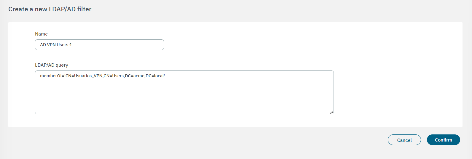
It is required to assign an LDAP Filter name and the LDAP/AD query. We can use different attributes and conditions: memberOf checks if a user belongs to a specific group; the group checked is Corporate_User that belongs to an organizational unit and this is part of the domain named mycompany.local.
Click on Confirm and you will see the new filter displayed in the table.
To enable the filter, click on the three-dot icon located at the end of the filter row. It will display the following options:
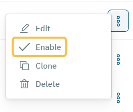
Select Enable to open the following dialog:
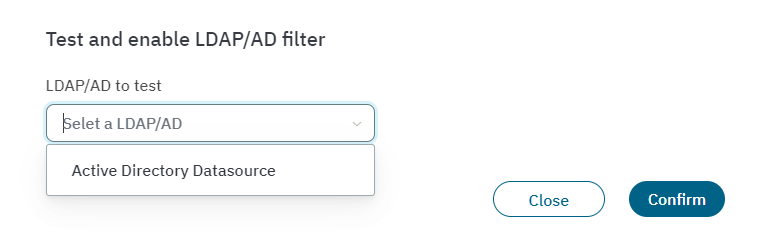
Choose the Active Directory to associate this filter with and click on the Confirm button. If no errors occur, it will enable the filter.
4.7.2.10.10. Setting the Firewall as a Network Device
In this step, you need to set the Firewall as a Network Device in the System data section.
Go to Configure > General > System data > User Devices.
Choose the Network device option from the device pool.
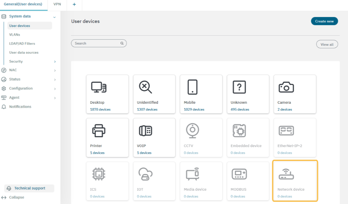
Once inside the network device view, click on Create new. It will display the following configuration window:
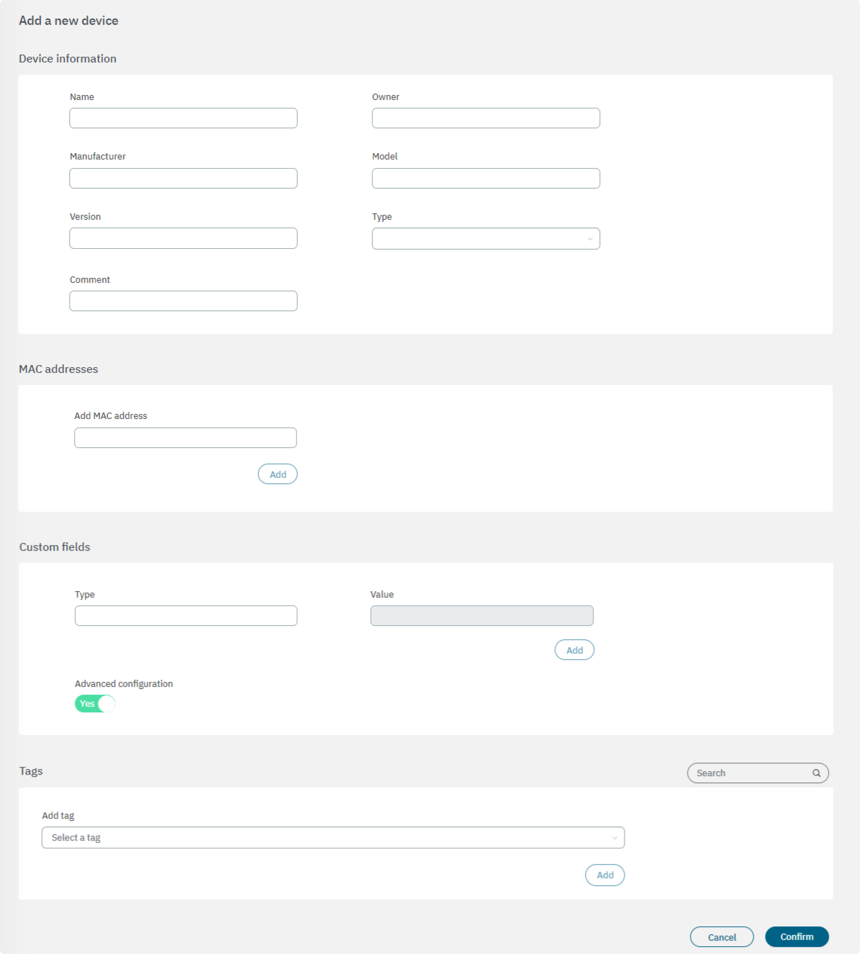
Device information
Name: Name you want to assign to the user device.
Owner: The owner of the user device.
manufacturer: The hardware manufacturer of the user device.
Model: The model of the user device hardware.
Version: The version of the user device
Type: Type of user devices. This can be a host or a phone device.
Comment: This can be used to include useful information to identify user devices.
MAC address
In this section, you can configure a MAC address or multiple MAC addresses associated with the user device. The MAC is one of the most important parameters as it is used to refer to the user devices in the Logs and in most of the tool modules. Also, if you are using the Agent, it can automatically group different MACs associated with a user device.
Custom fields
In this section, we can configure other parameters that are not already defined in the previous sections. You can define any parameter and its desired value by clicking on the Add button. You can use custom parameters to implement filters and locate a specific device with precision.
By enabling the Advanced configuration flag, it will display the Tags section.
Tags
From this field you can select a tag to associate to this device.
Click on Confirm to save your configurations.
4.7.2.10.11. Creating Policies
In this section, we will configure the VPN user validation policies. Here, we will create four policies as examples: one for admin users, one for standard users, one for Rejected users, and one for Visibility Agent.
Note
For the WireGuard VPN service, it is necessary to associate the appropriate WireGuard plugin during the configuration process. However, note that this configuration step is not required when using OpenVPN.
To associate the WireGuard plugin to a policy:
Go to the Configure > NAC > Policies section.
Open the Postconditions configuration of the policy you want to associate the WireGuard plugin with.
Enable the Apply plugin flag.
Scroll down to the last plugin of the list to find WireGuard.
Enable the WireGuard flag, and click on Apply config.
4.7.2.10.11.1. Creating an Admin User policy
Go to Configure > NAC > Policies
Click on the Create new button.
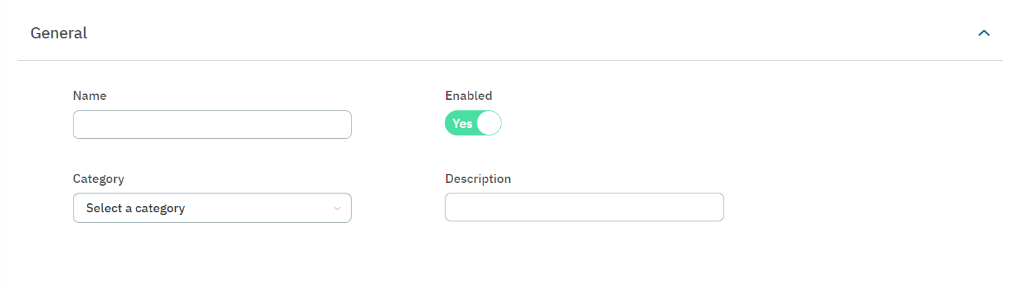
In the General section, add a policy name (Admin User), enable the policy and select a category. You can also add a descriptive comment to the new policy.
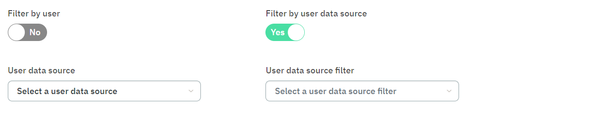
In the Preconditions section, enable the Filter by user data source flag and specify its user data source filter.
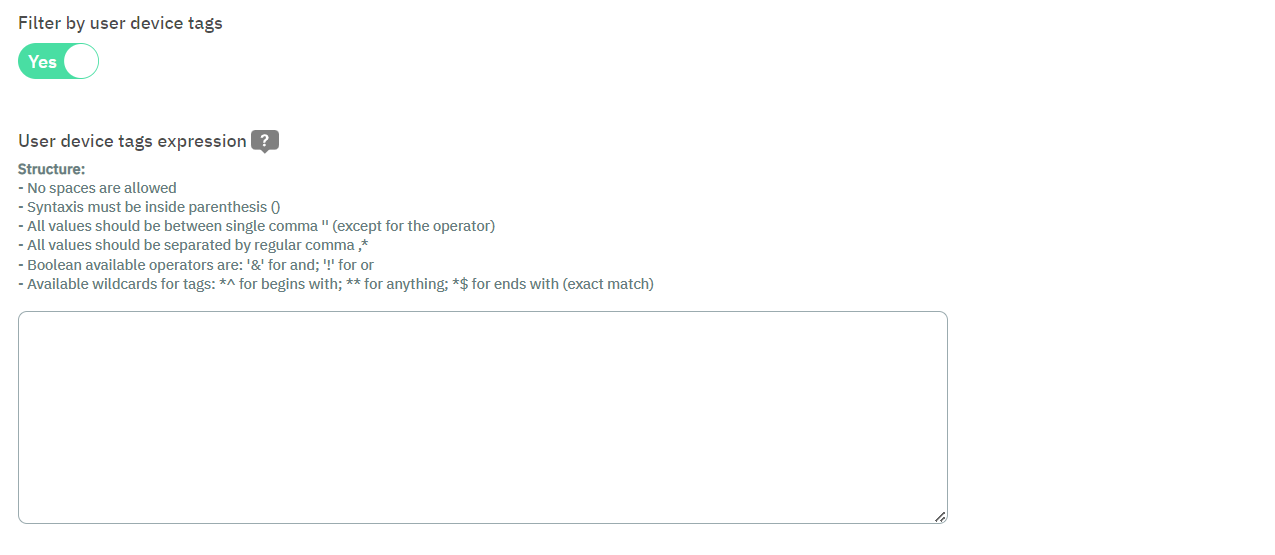
Still in Preconditions section, enable the Filter by session flag and introduce a tag expression for this policy. By clicking on the “?” sign, you can see examples of device tags expressions that you can copy and paste to the expression field.
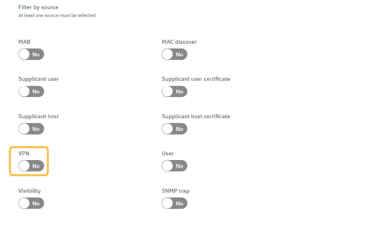
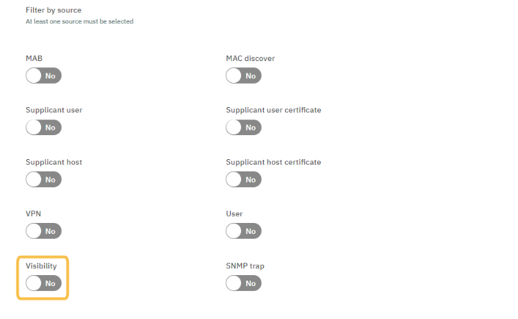
Still in the Preconditions section, scroll down to the Filter by source configuration and enable only the VPN flag.
In the Postconditions section, select the SWITCH DEFAULT VLAN.
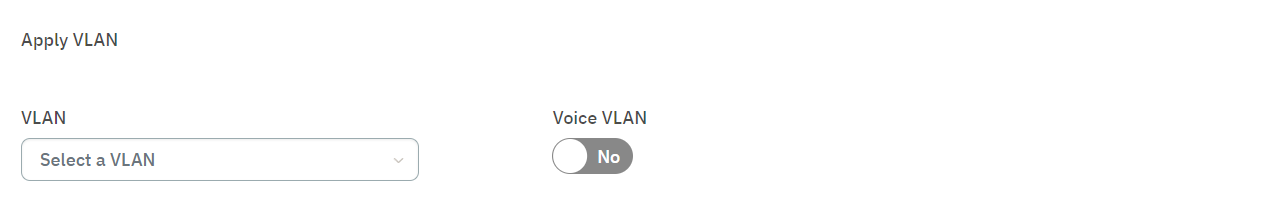
Scroll down to the Apply extra RADIUS param flag and enable it.
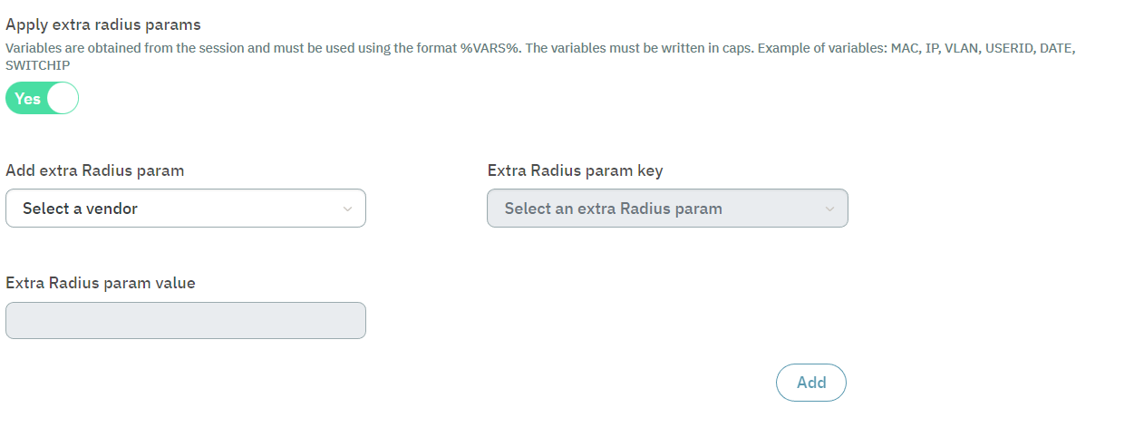
Add Extra RADIUS params: Set the vendor to opennac
Extra RADIUS param key: Select OpenNAC-VPNGW-Role
Extra RADIUS param value: Enter the name of the dynamic zone created earlier, which associates the group of AD users and the selected LDAP filter. This validation, along with the rule we are currently creating, automatically assigns the ACLs security policies upon completion.
Click on Confirm at the page bottom to save the configurations.
4.7.2.10.11.2. Creating a Standard User policy
Go to Configure > NAC > Policies and click on the Create new button.
In the General section, add a policy name (Standard User), enable the policy and select a category. You can also add a descriptive comment to the new policy.
In the Preconditions section, enable the Filter by user data source flag and specify its user data source filter.
Repeat steps 4, 5, and 6 of the Admin user policy.
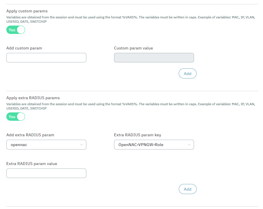
In the Postconditions section, you need to create a parameter with a new value. This parameter is used in the firewall to distinguish VPN networks. For WireGuard, the corresponding zone should be assigned in the Custom params field, whereas for OpenVPN, it should be assigned in the Extra Radius params field.
Click on Confirm at the page bottom to save the configurations.
4.7.2.10.11.3. Creating a Reject User policy
A Reject policy must be created to reject the connection of those users who do not comply with the rest of the VPN policies. This policy must be located at the end of all VPN policies.
Go to Configure > NAC > Policies and click on the Create new button.
In the General section, add a policy name (Reject User), enable the policy and select a category. You can also add a descriptive comment to the new policy.
In the Preconditions section, scroll down to the Filter by source configuration and enable only the VPN flag.
In the Postconditions section, select the ACCESS DENIED VLAN.
Click on Confirm at the page bottom to save the configurations.
4.7.2.10.11.4. Creating a Visibility Agent policy
This policy will assign an agent profile to all devices that have the Agent installed before they connect.
Go to Configure > NAC > Policies and click on the Create new button.
In the General section, add a policy name (Visibility Agent), enable the policy and select a category. You can also add a descriptive comment to the new policy.
In the Preconditions section, enable the Filter by user device tags expression and add the expression: (&,’^ONC_AGENT$’).
Still in the Precondition section, scroll down to Filter by source and enable the Visibility flag.
In the Postconditions section, select the SWITCH DEFAULT VLAN.
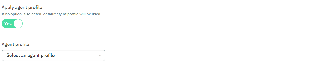
Still in the Postcondition section, select the agent profile previously created.
4.7.2.10.12. Configuring OTPs
This section explains how to configure One-time Passwords (OTP).
Go to Configure > Configuration > OTP.
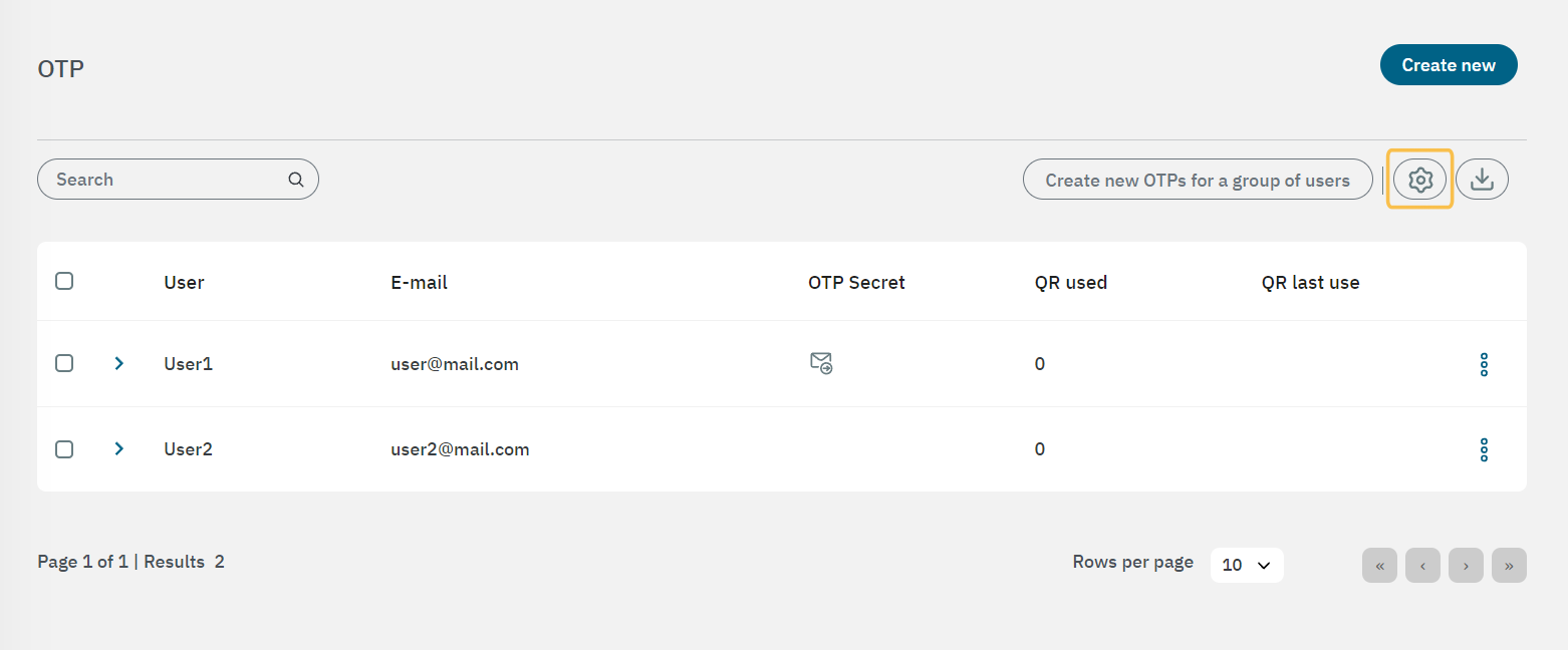
Click on the gear icon to open the OTP configuration window.
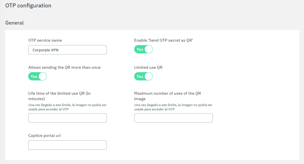
General
OTP service name: Enter a name for the OTP service.
Enable ‘Send OTP secret as QR’: Enable this flag so users can receive a QR code to be used in an authenticator service.
Allows sending the QR more than once: By default the QR Code can be sent only once (if you want to send another email, you must generate a new OTP secret). In case you want to reuse the same code, enable this flag.
Limited use QR: Flag that enables one-time QR mode.
Life time of the limited use QR (in minutes): Defines the time in minutes that a QR image will take to expire from when it is sent until it is scanned by the user.
Maximum number of uses of the QR image: Defines the maximum number of scans of the same QR image.
Captive portal url: Captive portal address for the one-time QR.
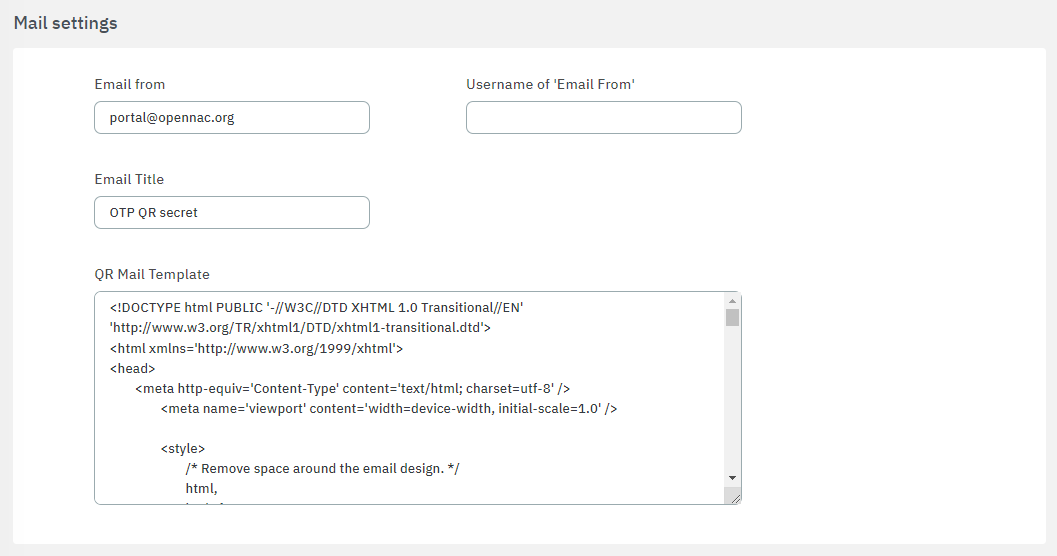
Mail settings
Email from: Enter the email address that will send the QR secret.
Username of ‘Email From’: Provide a descriptive name (e.g., the sender’s name or the organization’s name) instead of an email address, especially avoiding the same email address used in the “Email from:” field. This information is crucial to prevent potential rejection by mail relay servers due to anti-spam rules.
Email Title: Enter an email title, e.g. ‘OTP QR secret’.
QR Mail Template: HTML template for the email body.
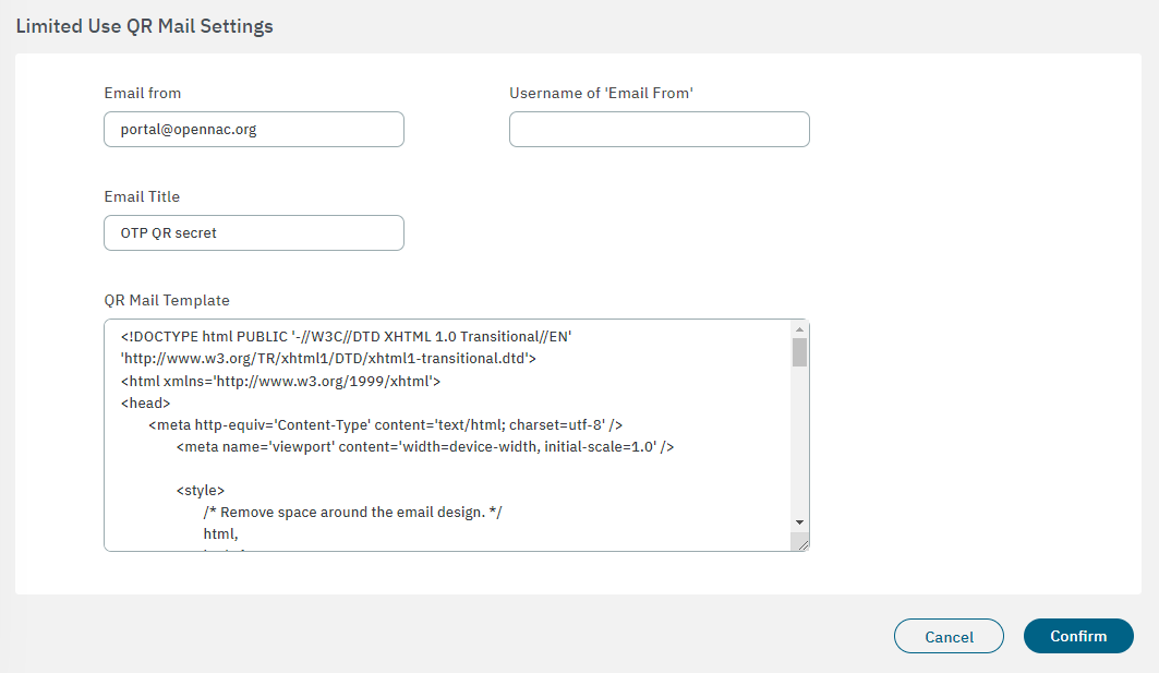
Limited Use QR Mail Settings
Email from: Enter the email address that will send the QR secret.
Username of ‘Email From’: Provide a descriptive name (e.g., the sender’s name or the organization’s name) instead of an email address, especially avoiding the same email address used in the “Email from:” field. This information is crucial to prevent potential rejection by mail relay servers due to anti-spam rules.
Email Title: Enter an email title, e.g. ‘OTP QR secret’.
QR Mail Template: HTML template for the email body.
Click on Confirm to save your configurations.
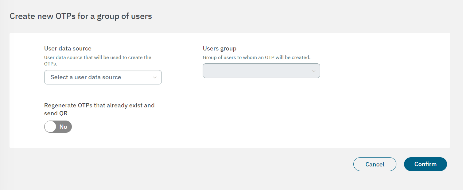
You can also create new OTPs for a group of users. By clicking on the corresponding button in the main view, you can create new OTPs for a group of users based on User Data Sources. Note that you must previously configure your UDS to have them available on this view.
For all the OTP administration options and management details, see the Configure > OTP section.