4.7.4. Configuration
To follow this configuration process, it is necessary that all nodes have been previously deployed for module operation (ON Core, On Analytics, ON Sensor, CMI, VPN Gateway), following the official node deployment guide.
4.7.4.1. Backend configuration
In this section, we will see the backend configuration for the 2SRA use case.
4.7.4.1.1. BE Configuration - ON Sensor
This section explains how to configure the ON Sensor interface so that it can receive the information sent by the VPN gateway.
4.7.4.1.1.1. Configure ON Sensor interface - Adapter
Access ON Sensor via SSH
Execute the script /usr/share/opennac/sensor/scripts/set_vxlan.sh
sh /usr/share/opennac/sensor/scripts/set_vxlan.sh -d <eth0> -l <172.16.1.1> -n 192.168.70.1/24
Where:
-d <eth0>: use the interface related to the IP of ON Sensor. DMZ network interface for communication with the FE.
-l <172.16.1.1>: use the ON Sensor IP previously configured. IP of the DMZ network for communication with the FE.
-n 192.168.70.1/24: network used for VXLAN communication.
Check that the FW service is stopped:
systemctl stop firewalld
systemctl disable firewalld
You can verify that the new virtual interface was added by running the following command
ip a
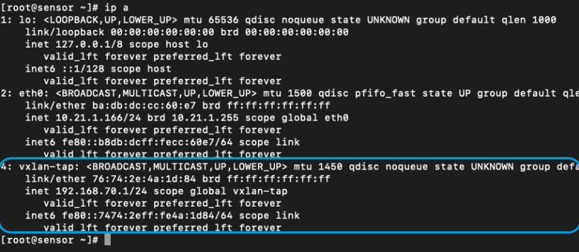
4.7.4.1.1.2. Configure ON Sensor interface - VXLAN Tunnel
Access ON Sensor via SSH
Edit the file /opt/zeek/etc/node.cfg modifying the “interface” line with the vxlan-tap interface
[zeek]
type=standalone
host=localhost
interface=vxlan-tap
In the case of combining the VPN use case with the Visibility one, in the configuration of the node.cfg file, it will be necessary to configure each of the interfaces used by workers’ modules.
Warning
If this is the case, it is necessary to delete the configuration mentioned before.
##Below is an example clustered configuration. If you use this,
## remove the [zeek] node above.

[logger-1]
type=logger
host=localhost
#
[manager]
type=manager
host=localhost
#
[proxy-1]
type=proxy
host=localhost
#
[worker-1]
type=worker
host=localhost
interface=vxlan-tap
#
[worker-2]
type=worker
host=localhost
interface=ens224
Restart the service
systemctl restart zeek
4.7.4.1.2. BE Configuration - ON Core
This section explains how to configure ON Core.
4.7.4.1.2.1. Notification Service Configuration
This section explains how to configure the SMTP Mail server in the ON Core so that it can send emails. The ON Core has to be able to send users the email with the QR code needed for the 2FA (Two-Factor Authentication).
4.7.4.1.3. Configuring SMTP Mail Relay
In this section we will configure the SMTP server in the ON Core so that it can send emails.
Connect via SSH to ON Core.
Update the system and install the necessary packages:
dnf update && dnf install postfix mailx cyrus-sasl cyrus-sasl-plain
SMTP Configuration:
There are two options for relaying the mail service: with authentication and without authentication.
When relaying without authentication, we utilize the SMTP protocol, and the configuration is as follows:
Configure postfix. In the relayhost section, add or modify the following lines in the
/etc/postfix/main.cf`file :
relayhost=[mail.acme.es]:25
     myhostname = mail.acme.es
Where:
relayhost: Specifies the mail relay host and port number. The hostname will be enclosed in parentheses to specify that an MX lookup is not required.
myhostname: hostname of the mail service.
Restart postfix service and enable auto startup:
systemctl enable postfix && systemctl start postfix
Send a test mail to verify the configuration:
mail -s "Test subject" recipient@domain.com < /dev/null
Where:
recipient@domain.com: Replace this with the recipient’s email address.
For the realization of this example, we relay on the Gmail mail service. Keep in mind that each email service will have specific configurations.
4.7.4.1.4. Postfix for emailing via Gmail
Update the system and install the necessary packages:
dnf update && dnf install postfix mailx cyrus-sasl cyrus-sasl-plain
Set up authentication with Gmail. Edit or create the
/etc/postfix/sasl_passwdfile and add the following line at the end:
[smtp.gmail.com]:587 <UserName@gmail.com>:<Password>
Where:
username@gmail.com: mail account
password: mail password
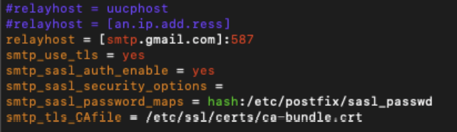
Configure postfix. In the
/etc/postfix/main.cffile, apply the following configurations for the relayhost section:
relayhost = [smtp.gmail.com]:587
smtp_use_tls = yes
smtp_sasl_auth_enable = yes
smtp_sasl_security_options =
smtp_sasl_password_maps = hash:/etc/postfix/sasl_passwd
smtp_tls_CAfile = /etc/ssl/certs/ca-bundle.crt
relayhost: Specifies the mail relay host and port number. The hostname will be enclosed in parentheses to specify that an MX lookup is not required.
smtp_use_tls: Enables transport layer security.
smtp_sasl_auth_enable: Enable SASL authentication.
smtp_sasl_security_options: This should be left empty to ensure that incompatible security options are not used.
smtp_sasl_password_maps: Specifies the password file to use. This is the file created in the Postfix configuration.
smtp_tls_CAfile: Specifies the list of certificate authorities to use when verifying the identity of the server.
See an example of this configuration below:
If your mail service is NOT authenticated, you should also edit the myhostname attribute of the
/etc/postfix/main.cffile with the name of your email domain.
myhostname = mydomain.tld
Compile and hash the contents of the
/etc/postfix/sasl_passwdfile:
postmap /etc/postfix/sasl_passwd
postmap hash:/etc/postfix/sasl_passwd
Restart the postfix service and enable autostart:
systemctl restart postfix && chkconfig --add postfix
In case of failure, perform the service shutdown and startup manually:
systemctl stop postfix
systemctl start postfix
Note
By default, Gmail only allows logins from secure connections.
To enable sending emails, it is necessary to change the settings in the Gmail account by enabling “Allow less secure applications”. For more information on how to do this, please review the information at the following link: https://support.google.com/accounts/answer/6010255?hl=en
Send a test mail to verify the configuration:
mail -s "Test subject" <recipient>@<domain.com> < /dev/null
Where:
recipient@domain.com: Replace this with the recipient’s email address.
To view all mail logs and other message information:
tail -f /var/log/maillog
4.7.4.1.5. Postfix for emailing via Office 365
Update the system and install the necessary packages:
dnf update
dnf install postfix cyrus-sasl-plain mailx
Set up authentication with Office365. Edit or create the
/etc/postfix/sasl_passwdfile and set the credentials:
[smtp.office365.com]:587 <UserName>@<DomainName>:<Password>

3. Configure postfix. In the :code:`/etc/postfix/main.cf` file, apply the following configurations for the *relayhost* section:
relayhost = [smtp.office365.com]:587
smtp_sasl_auth_enable = yes
smtp_sasl_password_maps = hash:/etc/postfix/sasl_passwd
smtp_generic_maps = hash:/etc/postfix/generic
smtp_tls_security_level = may
smtp_sasl_security_options = noanonymous
smtp_sasl_auth_enable: Enable SASL authentication.
smtp_sasl_password_maps: Specifies the password file to use. This is the file created in the previous step.
smtp_generic_maps: Optional lookup tables that perform address rewriting on the Postfix SMTP client, typically to transform a locally valid address to a globally valid address when sending mail over the Internet.
smtp_tls_security_level: By specifying a non-empty value, this overrides the deprecated smtp_use_tls, smtp_enforce_tls, and smtp_tls_enforce_peername parameters.
smtp_sasl_security_options: This should be left empty to ensure that incompatible security options are not used.
See an example of this configuration below:
Compile and hash the contents of the
/etc/postfix/sasl_passwdfile:
postmap /etc/postfix/sasl_passwd
postmap hash:/etc/postfix/sasl_passwd
Change the file permission:
chown root:postfix /etc/postfix/sasl_passwd
chmod 640 /etc/postfix/sasl_passwd
Configure the
/etc/postfix/genericfile to be able to send email from a valid user:
/.*/ <UserName>@<DomainName.tld>
Change the permission of the
/etc/postfix/genericfile, compile, and hash:
chown root:root /etc/postfix/generic
chmod 0600 /etc/postfix/generic
postmap /etc/postfix/generic
postmap hash:/etc/postfix/generic
Change the root alias to your email address in
/etc/aliases, now all messages sent to root will be forwarded to the system reporting address.
mailer-daemon:  postmaster
postmaster:    root
root:         <UserName>@<Domain.com>
Save and exit the file. Run the newaliases command to apply the changes.
Restart the postfix service and enable autostart:
systemctl restart postfix && chkconfig --add postfix
In case of failure, perform the service shutdown and startup manually:
systemctl stop postfix
systemctl start postfix
Send a test mail to verify the configuration:
mail -s "Test subject" <recipient>@<dominio.com> < /dev/null
Where:
recipient@domain.com: Replace this with the recipient’s email address.
To view all mail logs and other message information:
tail -f /var/log/maillog
4.7.4.1.5.1. RADIUS Request Authentication Configuration (only OpenVPN)
In this section the authentication of Radius requests will be configured.
Connect via SSH to ON Core
Edit the file “/etc/raddb/clients.conf”. Delete the configurations that do not correspond to the client scenario and add the following configuration for the addresses that will authenticate via Radius
client <shortname> {
   ipaddr          = <ip>
   secret          = <password>
}
Where:
ip: IP of the FE configured during the installation of the nodes.
password: desired password.
Note
This password must be entered during the creation of the authentication BackEnd in the CMI
4.7.4.1.5.2. Huntgroups file configuration (only OpenVPN)
In this section, we will configure the huntgroups file, which allows us to recognize VPN-type connections.
Connect via SSH to ON Core.
Edit the file “/etc/raddb/huntgroups”. Add the following line to the end of the configuration file using the IP of the VPN Gateway
vpn NAS-IP-Address == <IP _FrontEnd>
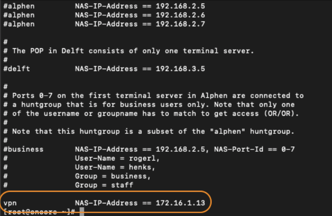
The “NAS IP Address” parameter will be used later, when we configure the VPN. See below the section where it will be used again:
Restart the radiusd service, to apply the latest changes.
systemctl restart radiusd
4.7.4.1.6. Configuration of Web Certificates
This section explains how to configure web certificates.
4.7.4.1.6.1. Let’s Encrypt web certificate creation
As reflected in the prerequisites, it is necessary to have a Web SSL certificate to avoid the bad user experience of receiving notifications in the user’s web browser and accepting exceptions.
Note
If you already have a company certificate, you can skip this step this step. In the case of not having a company certificate, we include the instructions to obtain one through Let’s Encrypt that allows you to generate certificates for free.
Let’s Encrypt certificates last for 3 months and must be renewed, either manually or automatically, before they expire. To make the request and generation of the certificate, it will be necessary for the FE machine to have Internet access and addressing to port 443 through the domain.
Connect via SSH to the FE
Install the acme.sh script
#Download and install acme.sh
curl https://get.acme.sh | sh -s email=<email_address>

#Update bash configuration
source ~/.bashrc
Stop the HAProxy service and create the certificate:
#Stop HAProxy
service haproxy stop

#Generate the certificate
acme.sh --issue --standalone -alpn -d <server_domain>
After carrying out the previous process, the certificate and its private key will have been created in a folder with the name of the domain entered when creating it: /root/.acme.sh/<server_domain>/fullchain.cer
Before entering it in the configuration, it’s necessary to create a new file that contains both the certificate and the private key. To create this single file, go to the path where the certificate was generated and execute:
#Access the directory
cd /root/.acme.sh/<server_domain>

#Combination of certificates
cat fullchain.cer <server_domain>.key > cert_emma.pem
4.7.4.1.6.2. Configuring web certificate in VPN Gateway
In this step, you must configure the VPN Gateway HAProxy service to use the previously generated HTTPS certificate.
Enter the certificate in the FrontEnd:
If we use a certificate generated by the company: Enter the certificate in the folder: “/etc/ssl/certs/” with the file name “cert_emma.pem” where the certificate and the corresponding key are located.
If we use a Let’s Encrypt certificate, from the FrontEnd use the file generated at the end of step 2.3.1.
Enable HTTPS configuration in HAProxy:
Uncomment (remove # from the start) the following lines inside the “FrontEnd” block of the “/etc/haproxy/haproxy.cfg” file:
#bind emmafront:443 ssl crt /etc/ssl/certs/cert_emma.pem no-sslv3 no-tlsv10 no-tls-tickets
#redirect scheme https code 301 if !{ ssl_fc }
#reqadd X-Forwarded-Proto:\ https
Restart the HAProxy service:
systemctl restart haproxy
4.7.4.1.7. BE Configuration - CMI
This section explains how to configure the CMI for 2sra use case.
4.7.4.1.7.1. Populate CMDB
Various objects can be stored in the CMDB of the CMI that can be used later in the FE.
The “CMDB FW Objects” are automatically synchronized every 5 minutes with the VPN Gateway. If you want to use it instantly, reopen the VPN gateway web portal.
To access the creation of VPN gateway objects, use the left side menu: “CMDB -> CDMD FW Objects”. On this screen there are already numerous predefined objects, mostly protocols.
To create a new object, click on the “Add new” button and fill in the information on the form.
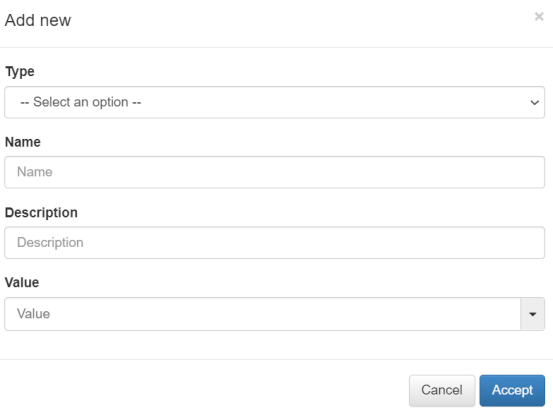
Where:
Type: Object type:
Network: One network. Ex: 172.16.1.0/24
Host: One concrete host. Ex: 172.16.1.13
Hosts: A list of hosts or IPs separated by commas.
Protocol: One protocol. Ex: tcp:443
Protocols: A list of protocols separated by commas.
Name: Identifier name of the object. It should only contain letters, numbers and underscore. It must not start with a number.
Description: Description of the object.
Value: Value of the object.
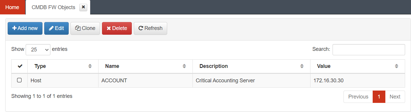
We are going to carry out an example by creating an object for the VPN Gateway, this will be a server from the network of critical servers.
Later on, we will configure a rule in the VPN Gateway using the object we have created, and as we can see in the images, the variable that we have created can be used to configure these rules.
For the example, we create the following object:
Type: Host
Name: ACCOUNT
Description: Critical Accounting Server
Value: 172.16.30.30
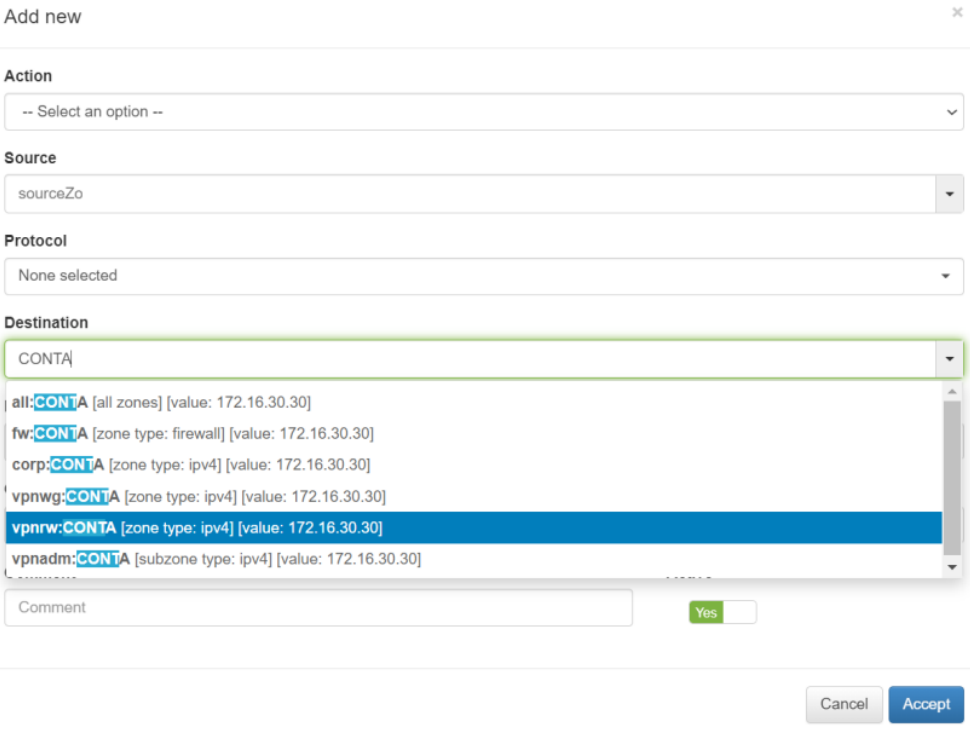
As mentioned before, if we access the VPN Gateway, we have the possibility to use the FW Object that we have created before when we define the FW Rules.
If the CMDB is not populated, we can execute the following command to populate it:
mysql -u root -p virtualapp < /usr/share/cmi-api/scripts/populate_cmdb_objects.sql
If we go to CMDB FW Objects we can see the following object that we need to edit with the corresponding CMI IP:
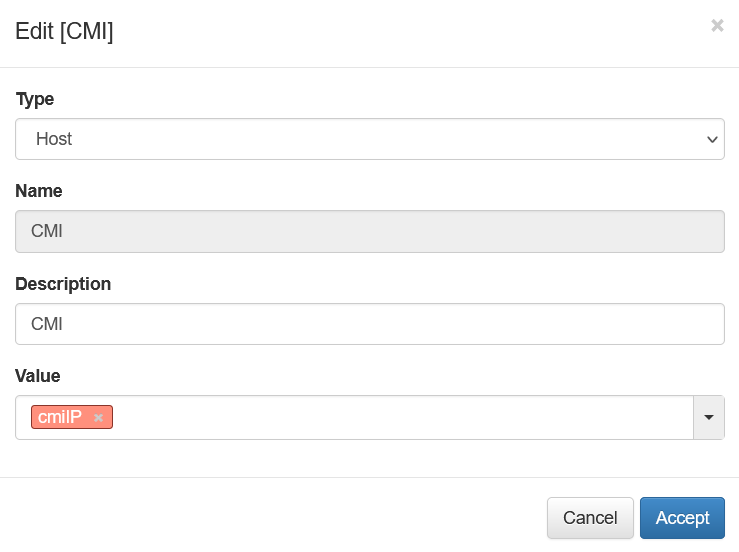
Finally, we will something like the following:
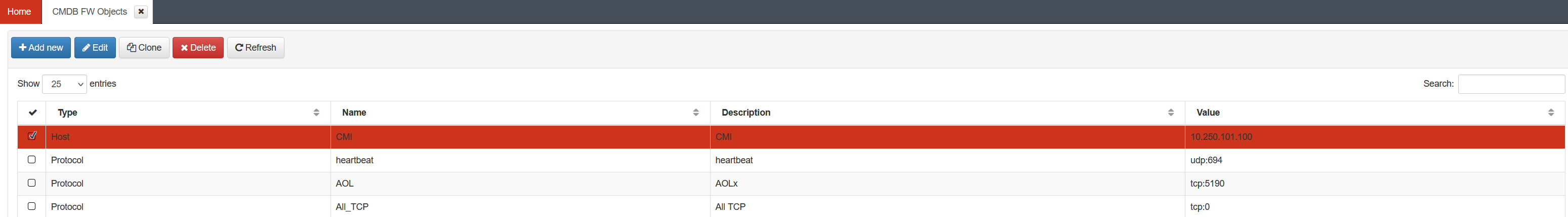
Note
The CMI IP value is an example. Put the corresponding one for your CMI.
4.7.4.2. VPN Gateway Configuration
This section explains how to configure the VPN gateway.
4.7.4.2.1. Configuration of the HAProxy service
In this step, the HA Proxy service will be configured. This service is used to redirect web traffic from the VPN Gateway to the onprincipal module in the BE, remember that you must allow different flows between the VPN Gateway and BE.
Edit the /etc/haproxy/haproxy.cfg file
In case you have not configured any certificate in step 2.3.2, the following lines must be commented out (add # at the beginning), this will force the use of port 80 for the connection:
#bind emmafront:443 ssl crt /etc/ssl/certs/cert_emma.pem no-sslv3 no-tlsv10 no-tls-tickets
#redirect scheme https code 301 if !{ ssl_fc }
#reqadd X-Forwarded-Proto:\ https
Remember to uncomment these lines once the certificate has been obtained and configured to be able to use port 443 with a server certificate.
To give permissions to access the administration panel from the public URL (not recommended) uncomment (remove # from the beginning) the following line:
#use_backend app if adminACL
Restart the service
systemctl restart haproxy
4.7.4.2.2. VPN Gateway web portal
The VPN Gateway configuration is done through the CMI web interface https://IP_CMI/
After logging in, the node management screen is accessed through the “Manage -> Appliances” menu. Select the VPN Gateway node and click the “Manage” button to access configuration management for that node.
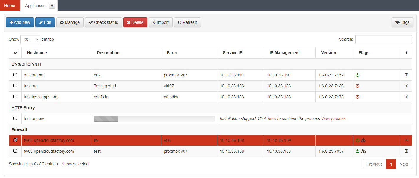
The web portal of the VPN Gateway will be opened.
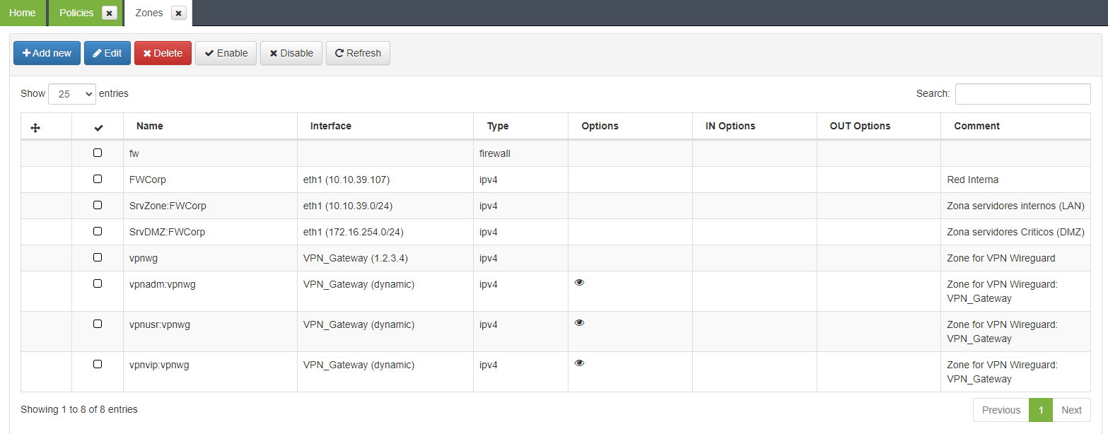
4.7.4.2.3. VPN Gateway Zones
The VPN Gateway is also a Layer 3 Firewall, which will allow us to easily manage the traffic flows of our VPN tunnel. The first step consists on identifying and configuring the different zones in which our network is segmented in order to manage traffic for the VPN. Using the example diagram in this document, we have defined the following zones:
FW - Frontend
FW Corp
Servers Zone
Servers DMZ
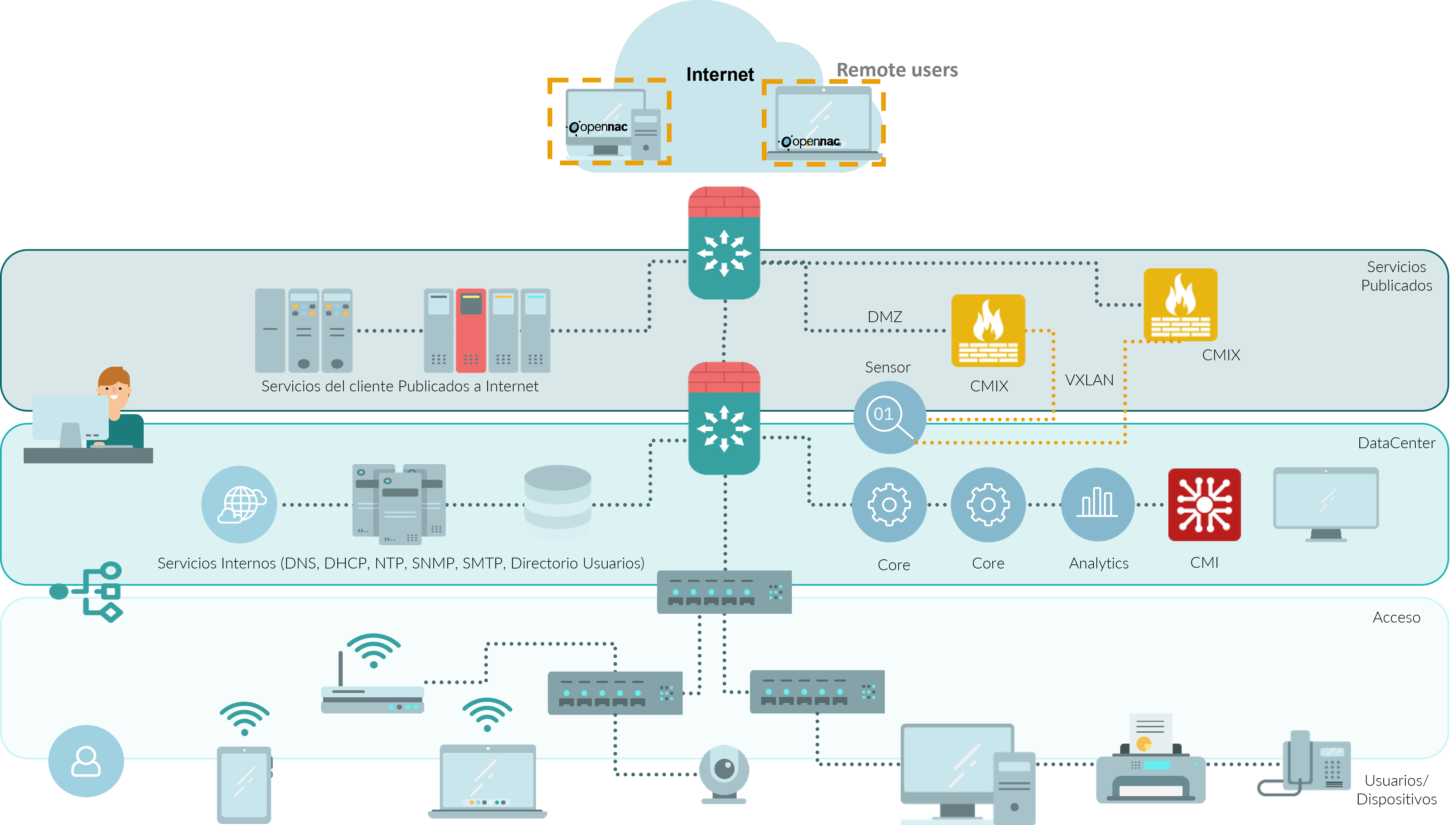
Keep in mind that the communication between the FE and the zones of standard and critical servers go through the FW Corp, therefore, these zones will be subzones of the previous one. So we need to create these zones and subzones by clicking “Manage -> Zones” in the zone management menu on the left side.
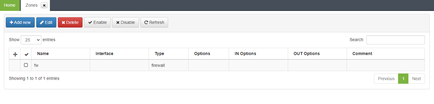
As can be seen in the table, the FE zone itself is already created by default. To create the rest of the zones, click on the “Add new” button and fill in the fields.
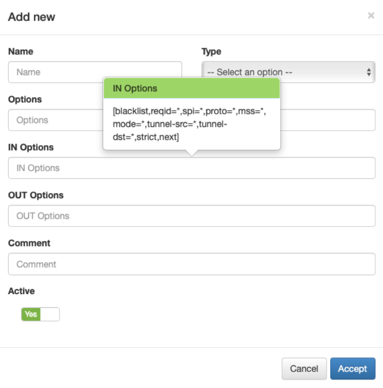
Where:
Name: name for the zone. Use short names. In the case of subzones
First create the parent zone. Example: “FWCorp”
Then create each subzone using the nomenclature “$Subzone:$Zone”. Example: “SrvZone:FWCorp”
Type: In the case of VPN, select IPv4
Comment: Fill in a descriptive comment if desired.
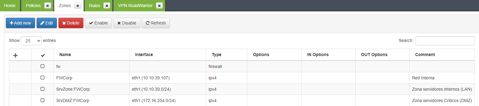
When we finish creating all the zones, we should see something like the following:
4.7.4.2.4. VPN Gateway Interfaces
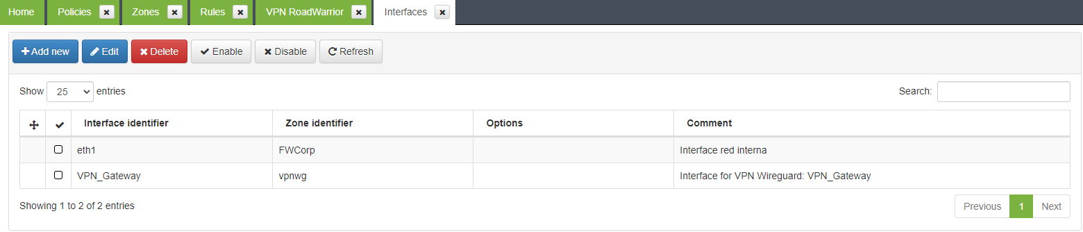
Once the zones are created, we have to assign them to a network interface (except the default fw zone). To do this, we click on “Manage -> Interfaces” in the interface management menu on the left side.
In this example, we only have one main zone (FWCorp). To assign this zone to the FE network, click on the “Add new” button and fill in the form
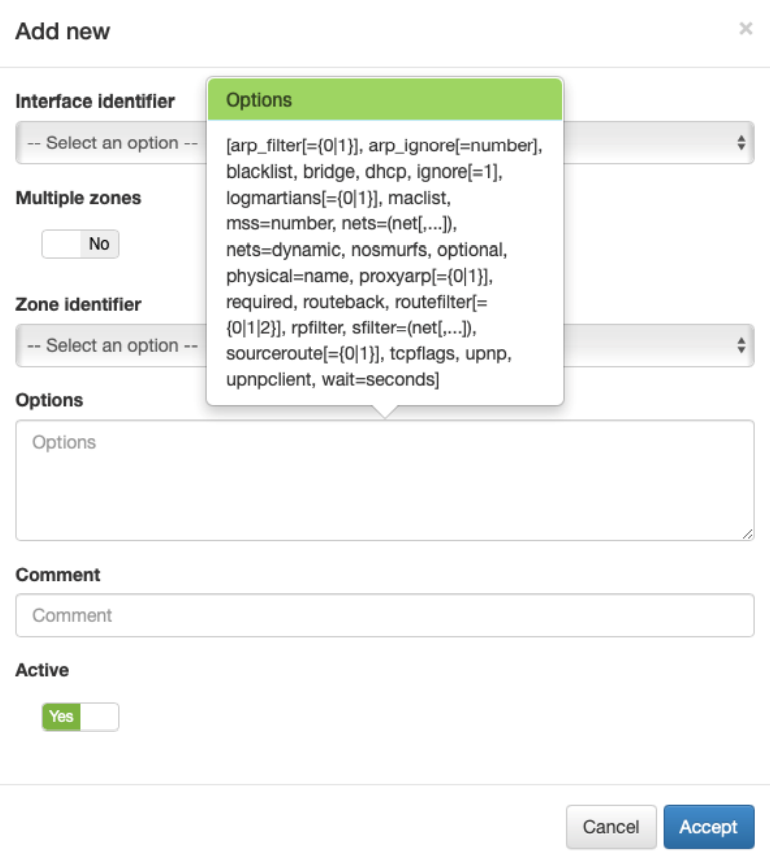
Where: - Interface Identifier: The network interface that you want to associate - Zone identifier: The zone that we want to associate to the previous interface. - Comment: Descriptive comment
In this example we select the only existing network interface, the FWCorp zone and save by clicking on the “Accept” button. It should appear like this:
4.7.4.2.5. VPN Gateway Hosts
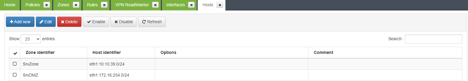
Previously, we have assigned the “FWCorp” zone to the VPN Gateway network interface. Host identification (in terms of subnets and/or individual IP addresses) is used to distinguish server subzones from the FWCorp zone. Find it on “Manage -> Hosts” in the Hosts management menu on the left side.
In the same way as in the previous cases, we click on the “Add new” button and fill in the fields displayed.
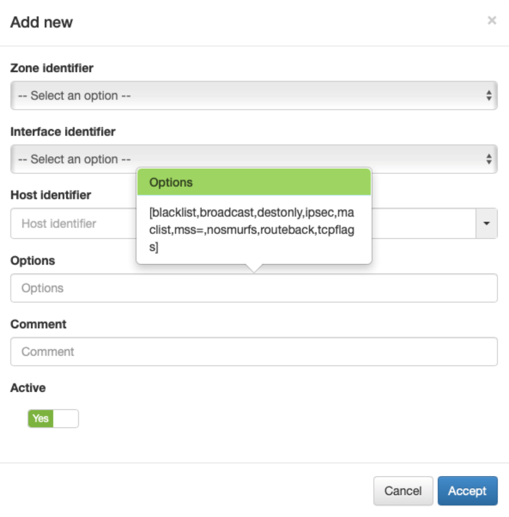
Where:
Interface identifier: Network interface with the main zone to associate.
Host identifier: Subnet to associate.
Zone idenfier: Zone identifier value
In our example, two forms would be filled in with the following information:
Host SrvZone:
Interface identifier: The only interface we have created.
Host identifier: 10.10.39.0/24
Zone idenfier: SrvZone
Host SrvDMZ:
Interface identifier: The only interface we have created.
Host identifier: 172.16.254.0/24
Zone idenfier: SrvDMZ
4.7.4.2.6. VPN Gateway Policies
Policies define the connections between previously defined zones in a high level. Initially, you need to create a policy that denies traffic between all defined zones. For this purpose, click on “Manage -> Policies” in the “Policies” management menu on the left side.
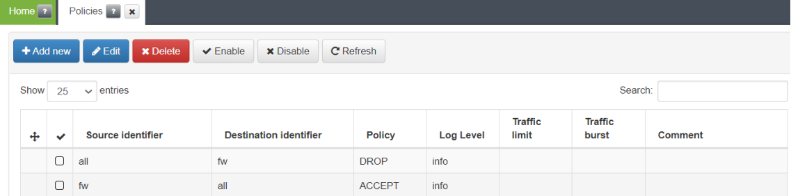
Next, press the “Add new” button to access the policy creation window:
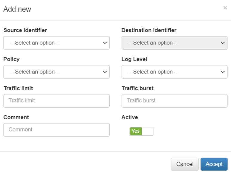
Where:
Source identifier: Zone from which the communication occurs.
Destination identifies: Zone to which the communication occurs.
Policy: Action we want to perform with the communication.
In our case, we will create policies from all the zones to all the zones with the action of discarding the communication, displaying a table like the following one:
4.7.4.2.7. VXLAN Monitoring rule
To allow VPN traffic monitoring, you need to create a rule that accepts UDP port 4789 traffic from any zone to the firewall.
To create the rule, from the VPN Gateway portal, we will go to the “Manage-> Rules” menu and create a new rule with the parameters shown in the following image:
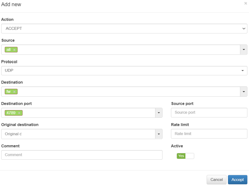
If we have previously created the “Destination port” in the CMBD of the CMI, within the menu “CMDB -> CMDB FW Object” as a new “Protocol” we could directly add the new protocol to the rule:
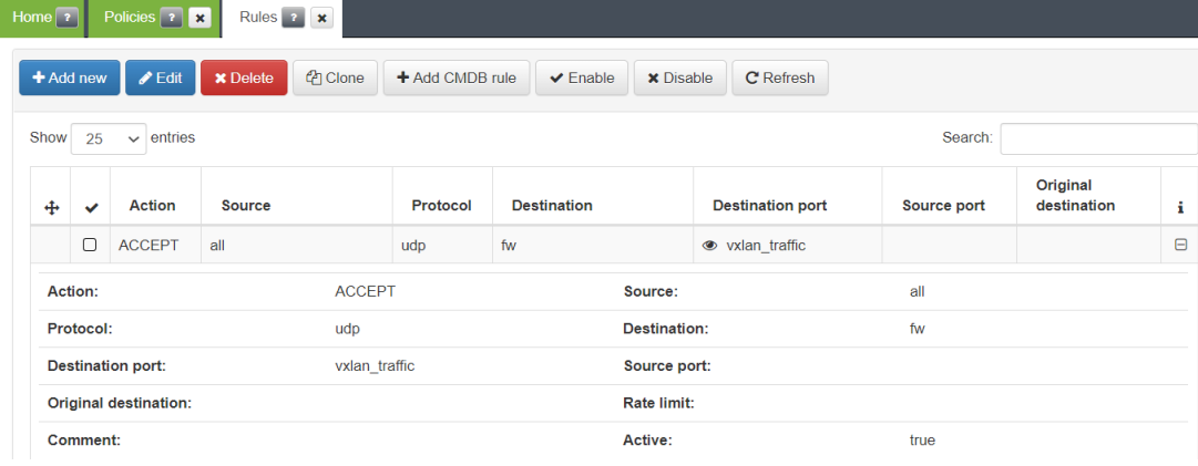
Some rules examples are the following:
4.7.4.2.8. Apply firewall configurations
When you finish configuring the VPNGW, you need to apply changes. In the same way, when changes are made to the configurations, it will be necessary to verify that they are correct and apply them. To carry out this action, we find the “FW” button in the upper right corner of the interface, which will open a service management menu after clicking on it.
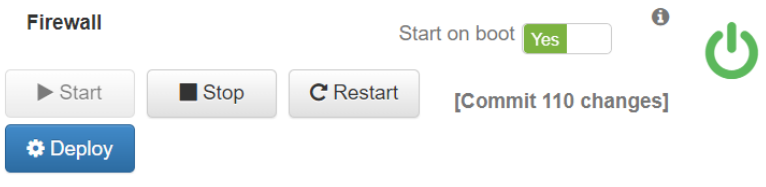
If you press the text “[Commit X changes]” a window with all the changes that the user has made on the firewall will open.
But the changes will not be applied until you click the “Deploy” button.
Clicking on that button, the configurations will be checked:
If the configurations are correct, the user will be informed and they will be applied automatically.
Otherwise, the user will be informed of the problem and they will not be applied, thus avoiding any problem.
4.7.4.2.9. VPN Roadwarrior
This section will explain the necessary configuration to start one of the two available RoadWarrior VPN systems:
OpenVPN
WireGuard
4.7.4.2.9.1. OpenVPN
This section shows how to configure OpenVPN.
4.7.4.2.9.1.1. CA Configuration
This section shows how to configure CA for OpenVPN.
A) Generate CA
It is necessary to have a certificate to associate to the Ipsec tunnel that we are going to create, so if you already have a PKI infrastructure you can use your own CA and the server certificates created with it. Go to the following section of this documentation to add your CA.
If you do not have your own CA or prefer to use a new one, follow these steps:
Access CMI via SSH.
Download easy_rsa to /opt and unzip it:
cd /opt
wget -c https://github.com/OpenVPN/easy-rsa/releases/download/v3.0.6/EasyRSA-unix-v3.0.6.tgz
tar xvzf EasyRSA-unix-v3.0.6.tgz
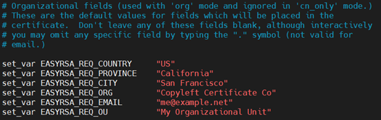
Edit and configure the variables file with the data of your organization:
Inside the directory /opt/EasyRSA-v3.0.6/, copy the “vars.example” file with name “vars” and modify its permissions
cd EasyRSA-v3.0.6/
cp vars.example vars && chmod +x vars
vim vars
Edit the newly created file “vars”.
Modify the following parameters accordingly with your organization:
Then you have to modify the expiration time of the CA and the certificates. You will need to uncomment the following lines and adapt the time according to your needs:
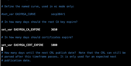
Having modified the default data, create your CA by following these steps:
Initialize the PKI environment:
./easyrsa init-pki
Create your CA: You will need to protect your CA with a strong password (write it down, as it will be needed in section “C) GENERATE A VPN SERVER CERTIFICATE USING THE CA”):
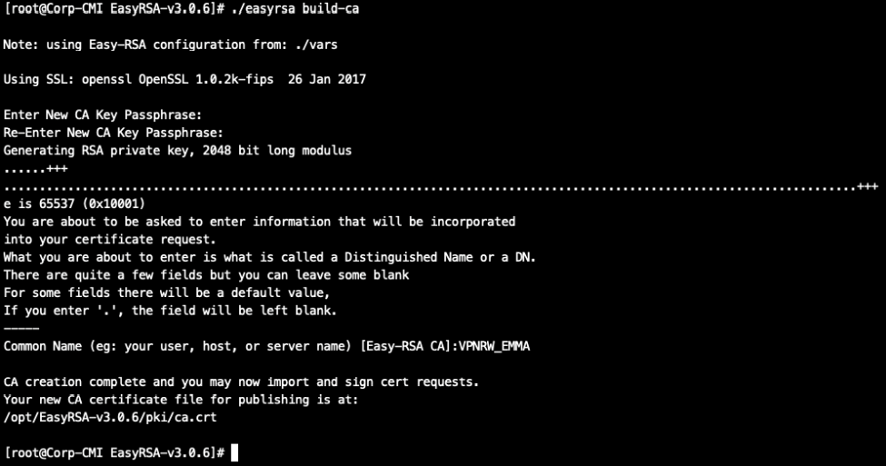
./easyrsa build-ca
It will ask you to enter a password and then a Common Name. In this example the Common Name is VPRW_EMMA:
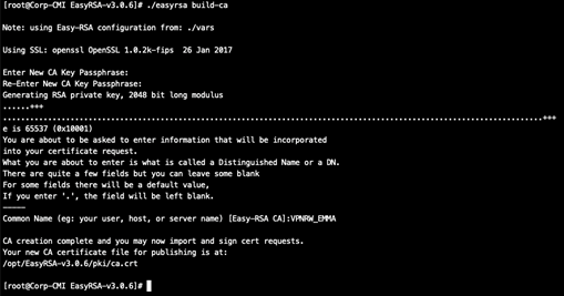
The CA will be available in the /opt/EasyRSA-v3.0.6/pki/ca.crt on the server. Copy it locally for later use.
scp root@<IP>:/opt/EasyRSA-v3.0.6/pki/ca.crt <LocalDirectory>
If you want to check that the certificate was created with the parameters used, use the following command:
openssl x509 -in /opt/EasyRSA-v3.0.6/pki/ca.crt -text -noout
B) Register the CA in the CMDB
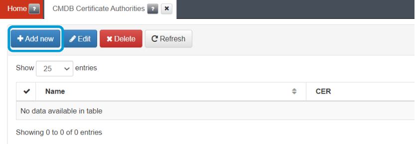
Once the CA has been created, it must be registered in the BackEnd so that it is available and can be used in the VPN Gateway.
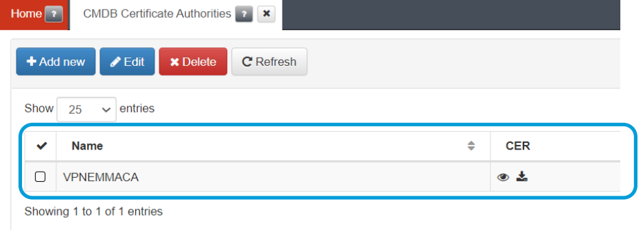
Connect to the management console and go to the “CMDB -> CMDB Certificate Authorities” menu and use the “Add new” button to add your CA:
Give the new CA a name and use the “Select” button to select the file with the CA. You can also copy the content of the CA directly into the certificate area.
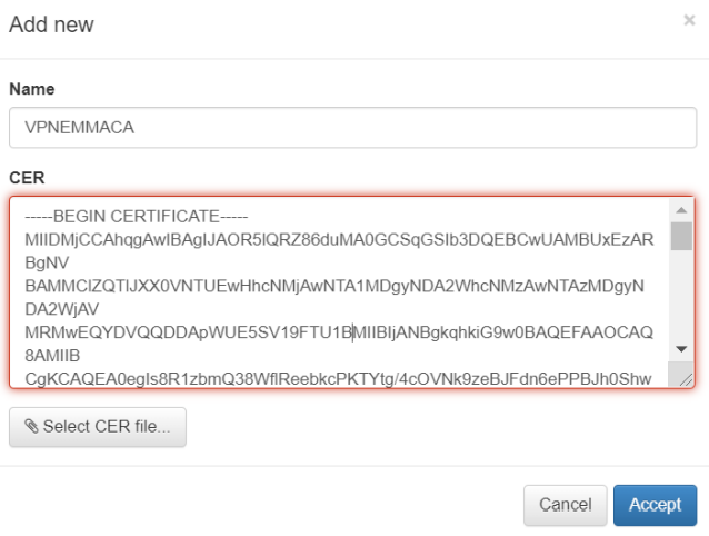
Click on accept and the CA will be loaded:
C) Generate a VPN server certificate using the CA
Once the CA is created, we can use it to create new certificates.
Generate a new CSR (new certificate request) and return to the same directory where the CA was generated and execute the following request:
./easyrsa gen-req VPN_EMMA_RW_SRV nopass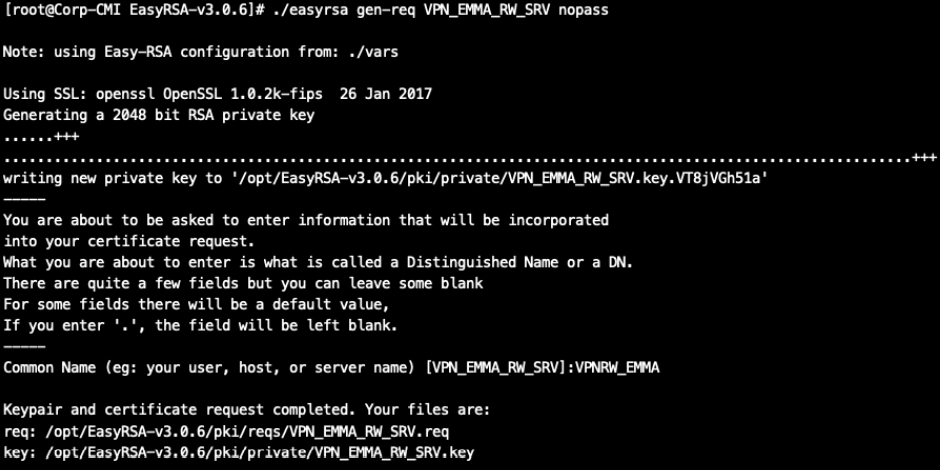
We will sign this request with our CA (for this we will need the password used in the section A-“Generate a CA”:
./easyrsa sign-req server VPN_EMMA_RW_SRV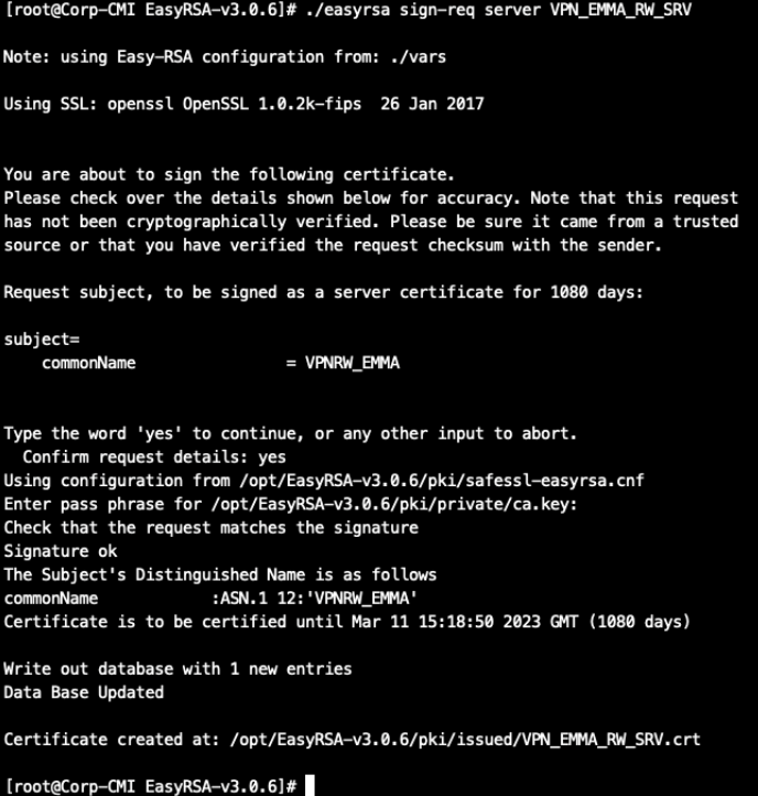
It will generate two files:
The certificate file: /opt/EasyRSA-v3.0.6/pki/issued/VPN_EMMA_RW_SRV.crt
The private key: /opt/EasyRSA-v3.0.6/pki/private/VPN_EMMA_RW_SRV.key
Copy both files to upload them to the management console for section D- “Register the server certificate in the CMDB”.
D- Register the server certificate in the CMDB
Once the server certificate has been created, it must be registered in the BackEnd so that it is available and can be used in the VPN Gateway.
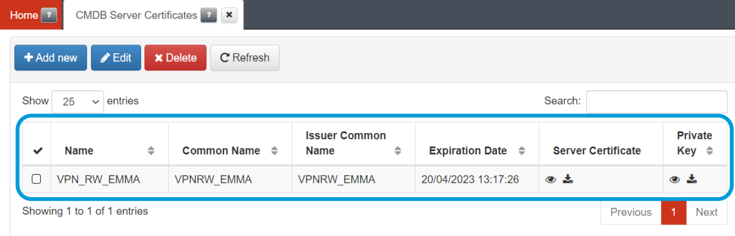
Connect to the administration console and go to the “CMDB -> CMDB Server Certificates” menu and use the “Add new” button to add your Certificate:
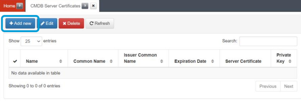
Give the certificate a name and use the “Select” button to select the file with the certificate, and then the private key. You can also copy the content directly into the certificate and private key area:
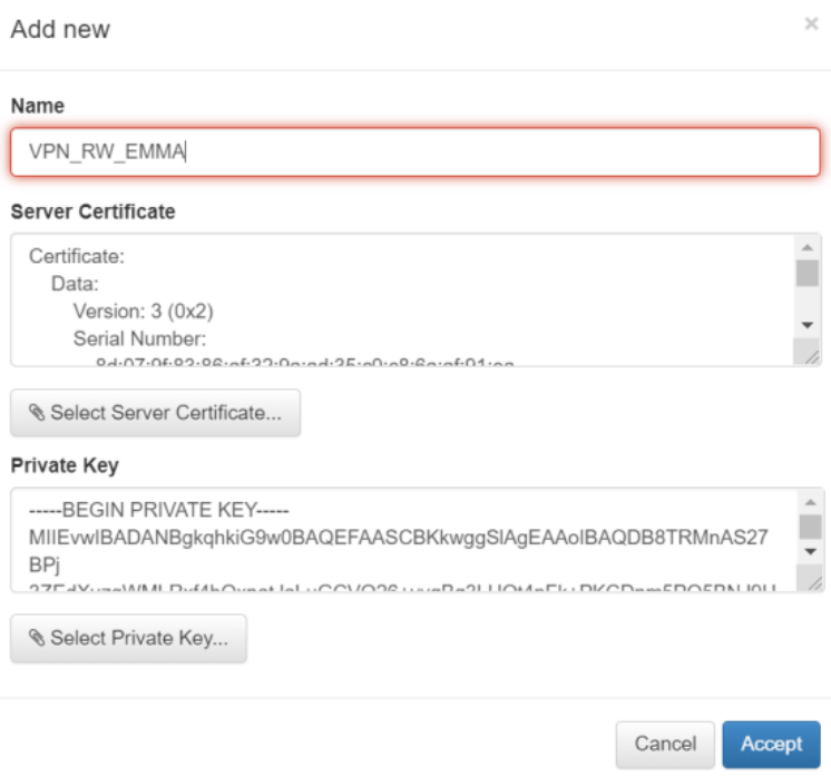
Click on accept and the CA will already be loaded
4.7.4.2.9.1.2. Configuration of the authenticator Core
To authenticate users in the VPN, it is necessary to select an authentication BackEnd during the process of creating said VPN. In the same way that we create objects in the CMDB, we are going to register this authentication BackEnd in the CMI.
Through the left side menu, we access the management of authentication BackEnds in the CMI (“CMDB -> CMDB BackEnd Authentication”) and click the “Add new” button to create a new one.
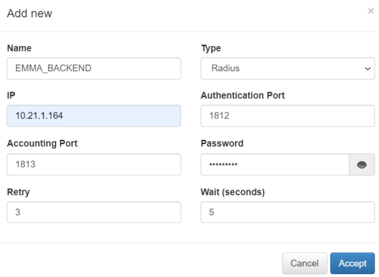
Where: - Name: Name to identify the backend
Type: Radius.
IP: ON Core IP Address
Authentication Port: 1812
Accounting Port: 1813
Password: Password previously set in the ON Core “/etc/raddb/clients.conf” file to allow authentications.
Retry: 3
Wait (seconds): 5
Note
If there has been any change after the initial configuration of these parameters, please enter the VPNGW management, edit the VPN connection and exit saving data to refresh the configuration. The changes will not be updated automatically if you do not complete this process.
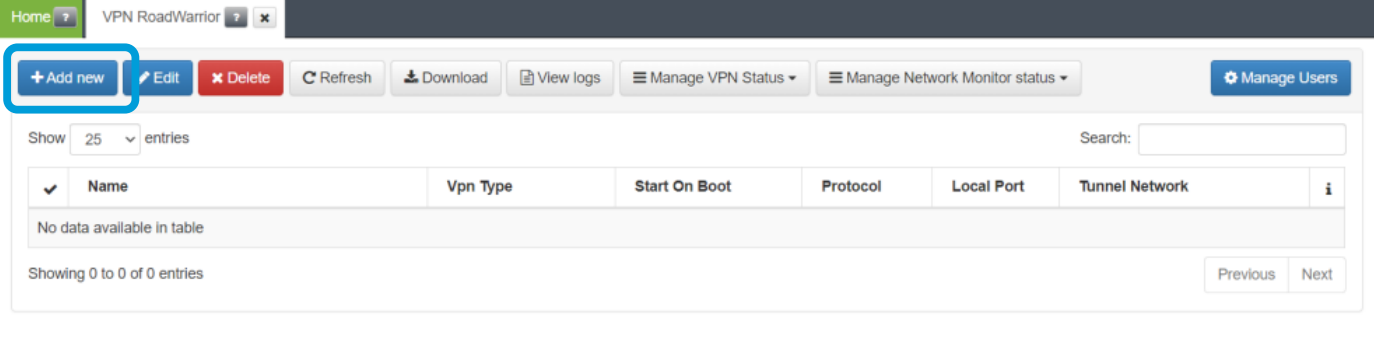
4.7.4.2.9.1.3. OpenVPN registration
This section explains how to create an OpenVPN type RoadWarrior VPN.
Access the VPN Gateway and open the management menu on the left side “Manage -> VPN RoadWarrior”.
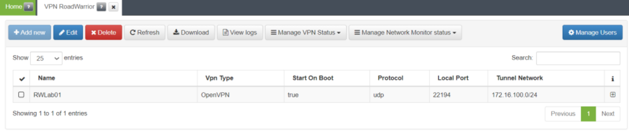
Click on the “Add new” button and a form containing three tabs will appear. Fill in the necessary information for each.
1- “General Information” tab OpenVPN form
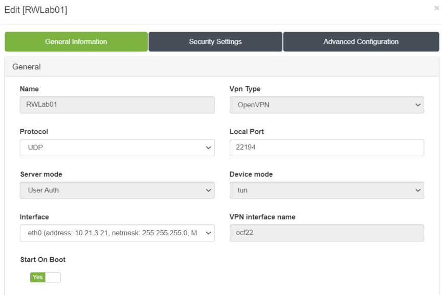
Where:
Name: Tunnel VPN name.
Vpn Type: Type of VPN to choose between WireGuard or OpenVPN.
Start On Boot: Enable if you want that the VPN Gateway starts when rebooting the machine. If it is off, you have to turn on the VPN manually after reboot.
Protocol: Protocol to use between [UDP, TCP]
Local Port: Local port for the clients request
Server Mode: The options that are in the configuration file will appear.
Device mode: Choose between tun or tap mode.
Interface: Network interface to be used.
VPN interface name: Name of the VPN interface (the final name of the interface will be formed by joining the device mode with this field).
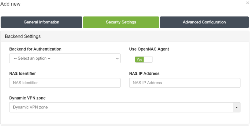
2- “Security Settings” tab OpenVPN form
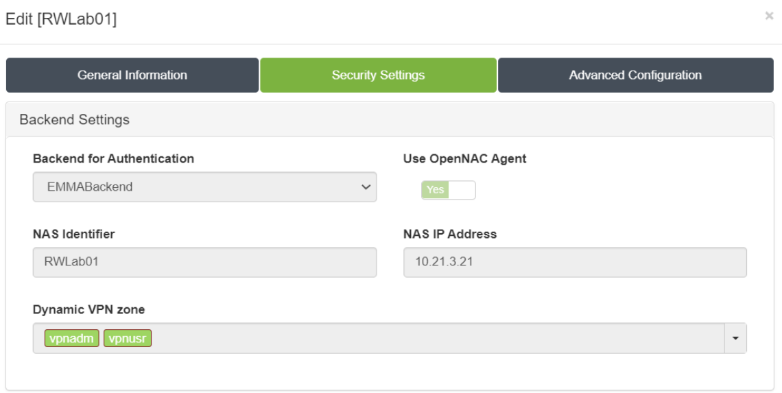
Where:
Backend for Authentication: Backend used to authenticate previously created users
Use OpenNAC Agent: Use the agent to establish the connection. Must be “yes”
NAS Identifier: Desired identifier for this VPN Gateway. It will be the one that appears in the radius logs.
NAS IP address: IP that is sent to the radius. It is the same ip that was previously configured in the huntgroups section above.
Dynamic VPN zone: Zones that will be dynamically associated to the VPN access groups. They will be used in the access policies that we will create later in the next chapter.
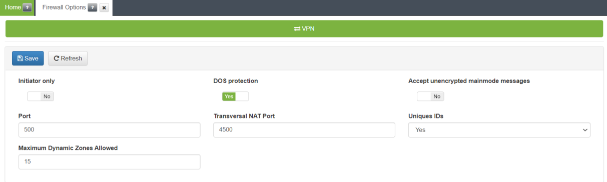
Note
ID can contain a maximum of 6 characters. The maximum number of dynamic zones is limited to 15, although the recommendation is 6-8 to facilitate the administration of “Policies”. To modify the maximum number of zones we will go to the “Manage -> Firewall Options” menu on the left side:
At the end of the “Security Settings” tab, we have to set the cryptographic settings.
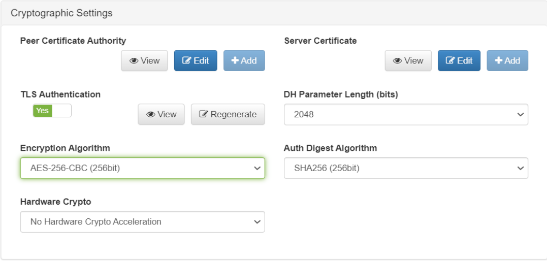
Where:
Peer Certificate Authority: Select the previously created CA
Server Certificate: Select the previously created server certificate.
TLS Authentication: Select if you want to use TLS, it should be “yes”.
DH Parameter Length (bits): The number of bits that the DH prime must have. Recommended minimum 2048
Encryption Algorithm: The encryption algorithm to be used. It’s recommended to use the AES-256-CBC algorithm
Auth Digest Algorithm: The algorithm to use to make the hash. It’s recommended to use the SHA256 algorithm
Hardware Crypto: If you have dedicated hardware for encryption select it. Dedicated hardware is NOT used in this guide.
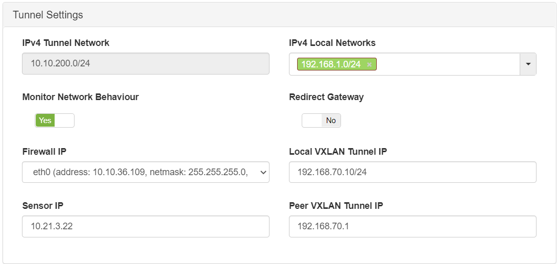
3- “Advanced Configuration” tab OpenVPN form
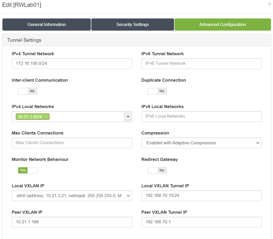
Where:
IPv4 Tunnel Network: Network in IPv4 CIDR format for remote users. Pool of IP addresses to be offered from the VPN Gateway.
Note
This network must not be in use within the organization.
IPv6 Tunnel Network: Network in IPv6 CIDR format for remote users. Pool of IP addresses to be offered from the VPNGW.
Note
This network must not be in use within the organization.
Inter-client Communication: If enabled, the communication between users who are connected in the VPN will pass only through the VPN server. if it’s disabled, the communication will reach the IP layer (therefore, the firewall rules will apply for this communication).
Duplicate Connection: If enabled, multiple connections with the same user are allowed, so a certificate can be used by more than one connection / user. If disabled, each VPN certificate must have its own CN, so each connection/user has a unique certificate.
IPv4 Local Networks: Local networks in CIDR IPv4 format that can be accessed through the VPN. When the connection is established, the connection routes are sent to the client so that it knows these networks.
IPv6 Local Networks: Local networks in CIDR IPv6 format that can be accessed through the VPN. When the connection is established, the connection routes are sent to the client so that it knows these networks.
Max Clients Connections: Maximum number of users that can connect on the VPN.
Compression: Choose the type of compression to use, recommended “Enabled with Adaptive Compression”.
Monitor Network Behaviour: If enabled, the traffic that is passing through the VPN connection will be monitored.
Important
A VXLAN tunnel will be created within our network, so it is necessary to enable traffic between the Frontend and Backend ON Sensor.
Redirect Gateway: If enabled, all traffic, including internet traffic, is redirected via VPN. In this case it is necessary to configure the DNS so that the resolution is internal. If disabled, only local networks will be accessed by VPN access.
Local VXLAN IP: IP address associated with the network interface through which the tunnel will be established for traffic monitoring with the BackEnd ON Sensor.
Local VXLAN Tunnel IP: Local IP address in IPv4 CIDR format for the VPN Gateway inside the tunnel for traffic monitoring.
Peer VXLAN IP: IP address of the BackEnd ON Sensor.
Peer VXLAN Tunnel IP: Remote IP address for the BackEnd ON Sensor inside the tunnel for traffic monitoring.
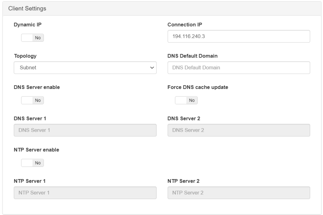
Dynamic IP: Allow the VPN to assign IPs dynamically.
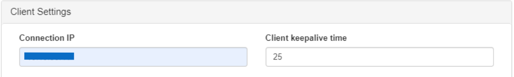
Connection IP: Public IP through which remote clients will connect to the VPN.
Note
You must have a public DNS record and an SSL certificate.
Topology: Type of network connection, by default is set to subnet.
Optional fields:
DNS Default Domain: Default domain name
DNS Server enable: Enable the configuration of the DNS servers.
Force DNS cache update: Force clearing the client’s DNS server cache.
DNS Server 1: Fill in if you want to use a specific DNS server.
DNS Server 2: Fill in if you want to use another specific DNS server.
NTP Server enable: Enable the configuration of the NTP servers.
NTP Server 1: Fill in if you want to use a specific NTP server.
NTP Server 2: Fill in if you want to use another NTP server.
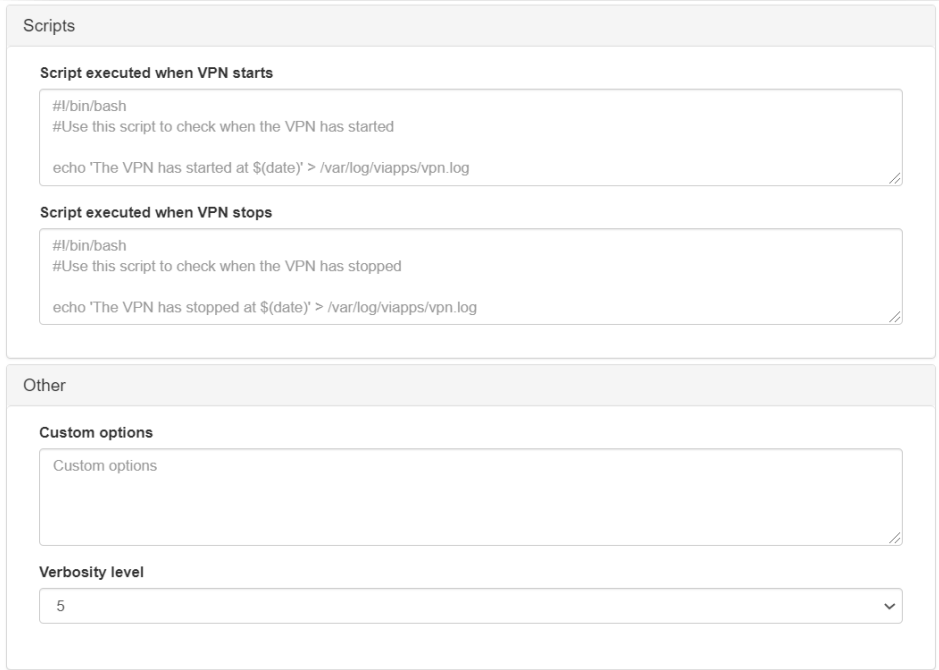
Script executed when VPN starts: Script that is executed when starting the VPN.
Script executed when VPN stops: Script that is executed when shutting down the VPN.
Custom options: Add extra parameters if necessary.
Verbosity level: The level of “log” information for the VPN.
4.7.4.2.9.2. WireGuard
This section shows how to configure Wireguard.
4.7.4.2.9.2.1. WireGuard VPN registration
This section explains how to create a WireGuard-type RoadWarrior VPN.
Access the VPN Gateway and open the management menu on the left side “Manage -> VPN RoadWarrior”.
Click on the “Add new” button and a form containing 3 tabs will appear. Fill in the necessary information for each
1) “General Information” tab WireGuard form
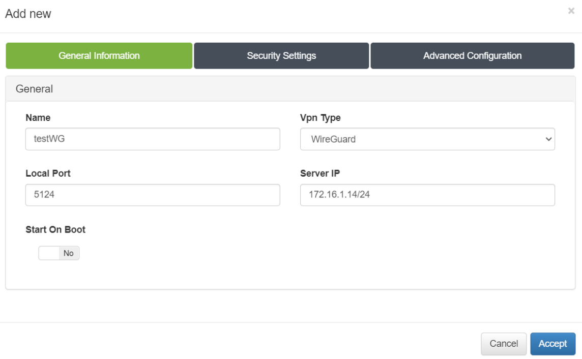
Where:
Name: Tunnel VPN name.
Vpn Type: Type of VPN to choose between WireGuard or OpenVPN.
Start On Boot: Enable if you want that the VPN Gateway starts when rebooting the machine. If it is off, you have to turn on the VPN manually after reboot.
Server IP: IP to use on the WireGuard network interface on the VPN Gateway server.
Local Port: Local port for the clients request
2) “Security Settings” tab WireGuard form
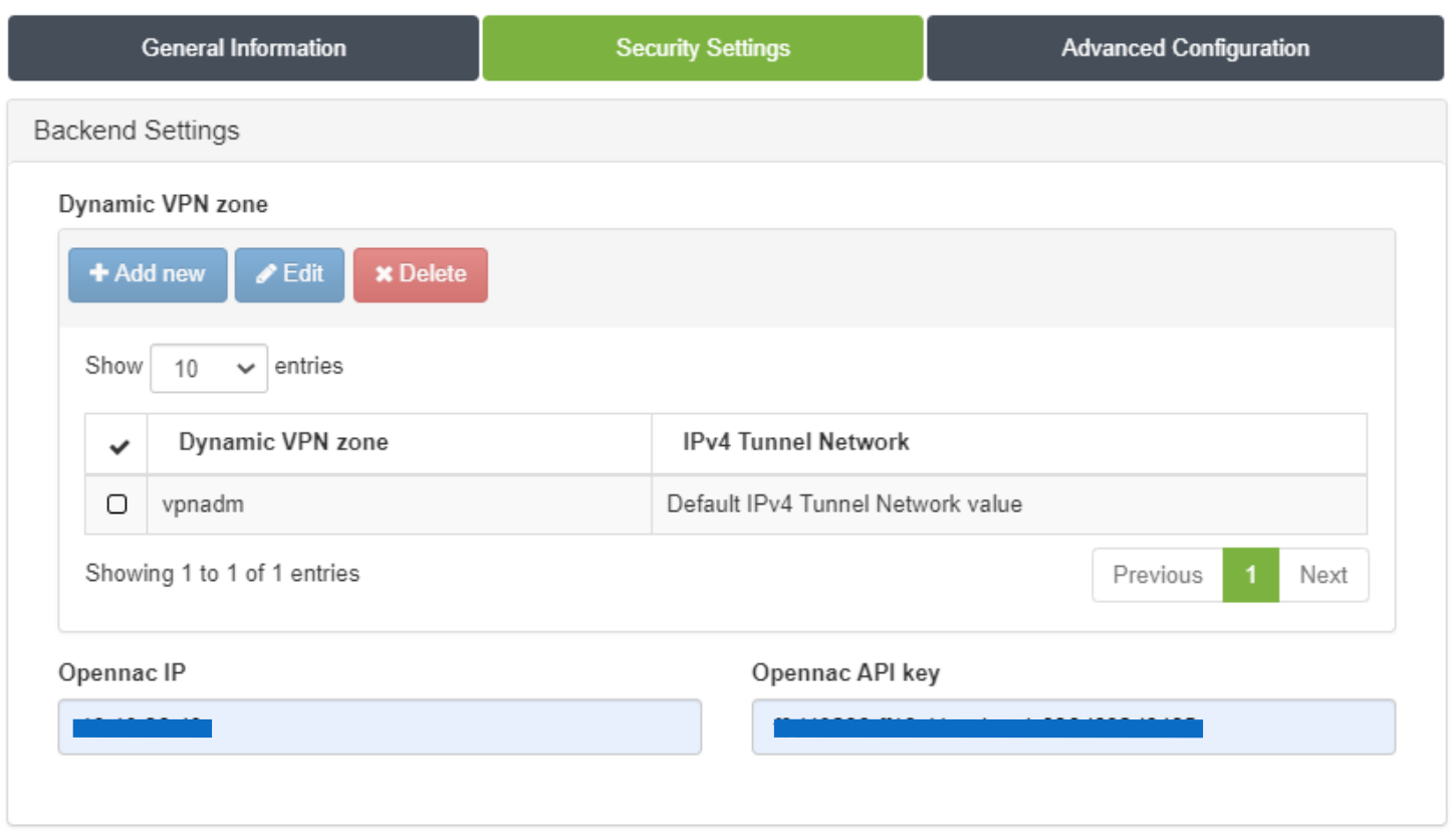
Where:
Dynamic VPN zone: Zones that will be dynamically associated to the VPN access groups. They will be used in the access policies that we will create later in the next chapter.
Note
For each dynamic zone you can assign the “IPv4 Tunnel Network” by default or create a different one.
Opennac IP: IP of the ON Core associated with this environment.
Opennac API key: API key of the ON Core associated with this environment for authentication against the ON Core API.
Note
ID can contain a maximum of 6 characters. The maximum number of dynamic zones is limited to 15, although the recommendation is 6-8 to facilitate the administration of “Policies”. To modify the maximum number of zones we will go to the “Manage -> Firewall Options” menu on the left side:
To register the API Key, open the ON Core administration portal and go to the “ON CMDB -> Security -> API key” menu.
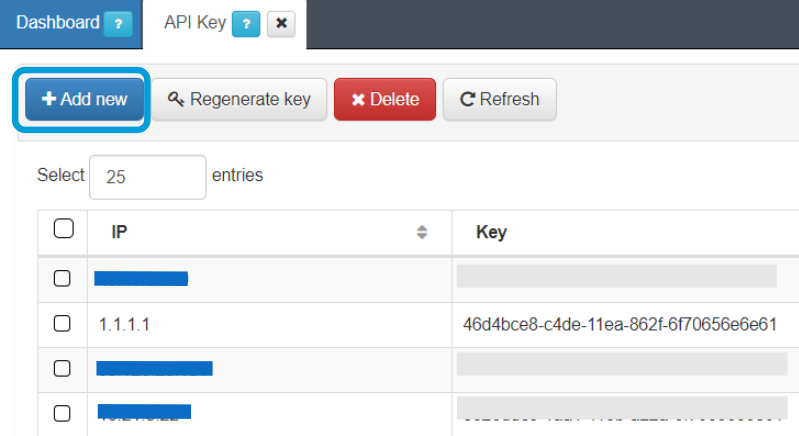
Click “Add new”:
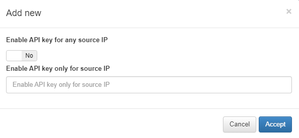
If there is more than one VPNGW, we will select the option Enable API key for any source IP, otherwise, we will enter the VPNGW IP in Enable API key only for source IP.
3) “Advanced Configuration” tab WireGuard form
Where:
IPv4 Tunnel Network: Network in IPv4 CIDR format for remote users. Pool of IP addresses to be offered from the VPN Gateway. NOTE: This network must not be in use within the organization.
IPv4 Local Networks: Local networks in CIDR IPv4 format that can be accessed through the VPN. When the connection is established, the connection routes are sent to the client so that it knows these networks.
Monitor Network Behavior: If enabled, the traffic that is passing through the VPN connection will be monitored.
Note
A VXLAN tunnel will be created within our network, so it is necessary to enable traffic between the Frontend and Backend ON Sensor
Redirect Gateway: If enabled, all traffic, including internet traffic, is redirected via VPN. In this case it is necessary to configure the DNS so that the resolution is internal. If disabled, only local networks will be accessed by VPN access.
Local VXLAN IP: IP address associated with the network interface through which the tunnel will be established for traffic monitoring with the BackEnd ON Sensor.
Local VXLAN Tunnel IP: Local IP address in IPv4 CIDR format for the VPN Gateway inside the tunnel for traffic monitoring.
Sensor IP: IP address of the BackEnd ON Sensor.
Peer VXLAN Tunnel IP: Remote IP address for the BackEnd ON Sensor inside the tunnel for traffic monitoring.
Connection IP: Public IP through which remote clients will connect to the VPN. NOTE: You must have a public DNS record and an SSL certificate.
Client keepalive time: How often a keepalive packet is sent to keep the connection active (in seconds).
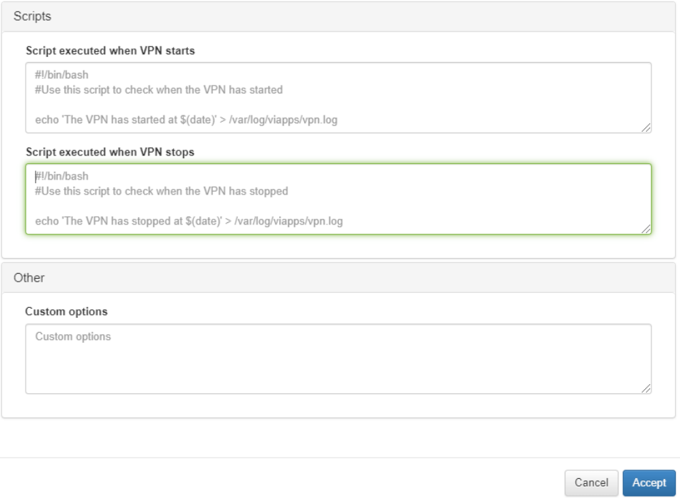
Script executed when VPN starts: Script that is executed when starting the VPN.
Script executed when VPN stops: Script that is executed when shutting down the VPN.
Custom options: Add extra parameters if necessary.
Finally we press the Accept button to create the VPN RoadWarrior.
If we want to manage the Users for our VPN, we need to go to the Manage Users button.
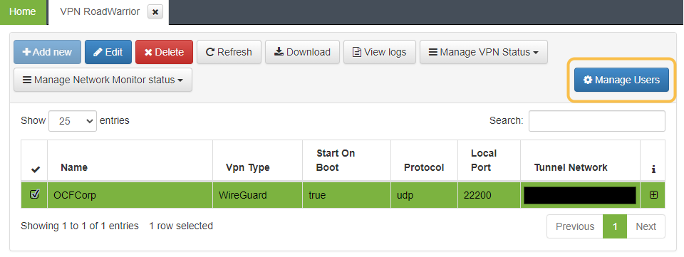
A new window will with all the users:
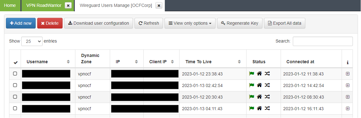
To create a new one, we need to click the Add new button and add the following information:
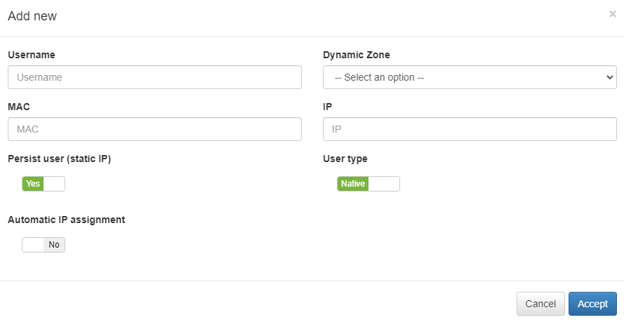
Username: Name of the user.
Dynamic Zone: Dynamic zone where the user belongs.
MAC: MAC address for that user.
Time To Live: Date until the user connection remains active.
IP: Assing the IP for a persist user.
Persist user(static IP): Assing a static IP to the user.
User type: Can be Native or Agent. Defines the type of the user.
Automatic IP assignment: Assings the IP automatically for a persist user.
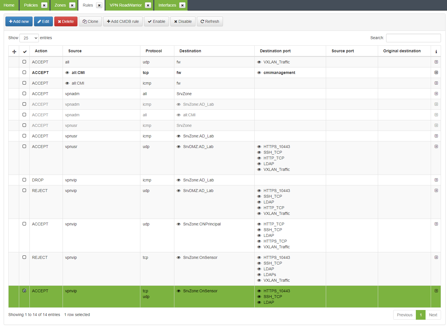
4.7.4.2.9.2.2. VPN RoadWarrior Permits
When creating the VPN tunnel, the necessary objects are automatically created in the VPN Gateway (Zones, interfaces, policies, etc.).
The policies created by default deny the traffic, so we must create the necessary policies and rules to allow the traffic between the different static and/or dynamic zones created by the tunnel
Access the “Manage -> Policies” policies in the “Policies” management menu on the left side and edit or create the necessary policies to allow traffic between the different zones.
Order the policies according to the environment needs
Our objectives are the following:
Allow VPN communications.
Allow the “administrators” group to access both standard and critical servers.
Allow the “users” group to access the standard servers.
Allow, using an exception, this group to access the critical server.
Block all other traffic.
In our example it would look like this:
Apart from the policies (which have a more generic nature), particular rules can also be generated to allow or deny traffic between computers, specific ports, etc.
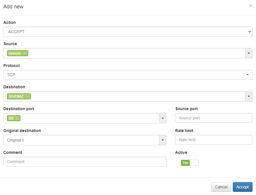
For our example, we are going to create a rule that allows the standard VPN user group to access the a DMZ server via HTTP port (80/tcp).
We access the rules management screen using the left side menu: “Manage -> Rules”.
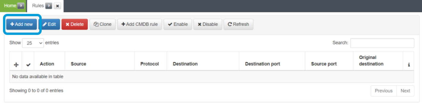
On this screen, and by clicking on Add new, we can create rules to allow or reject specific communication flows.
4.7.4.3. Component flows
Source |
Destination |
Port |
Service |
|---|---|---|---|
CORE |
MTA Relay |
TCP/587 |
SMTP SSL |
CORE |
MTA Relay |
TCP/25 |
SMTP |
CORE |
NTP SERVER |
UDP/123 |
NTP |
CORE |
DNS |
UDP/53 |
DNS |
CORE |
AD SERVERS |
UDP/TCP/88 |
KERBEROS |
CORE |
AD SERVERS |
UDP/TCP/135 |
DCOM/RPC |
CORE |
AD SERVERS |
UDP/TCP/137 |
NETBIOS |
CORE |
AD SERVERS |
UDP/TCP/138 |
NETBIOS |
CORE |
AD SERVERS |
UDP/TCP/139 |
NETBIOS |
CORE |
AD SERVERS |
TCP/389 |
LDAP |
CORE |
AD SERVERS |
TCP/445 |
SMB |
CORE |
AD SERVERS |
TCP/464 |
KPASSWD |
CORE |
AD SERVERS |
TCP/636 |
LDAPs |
CORE |
AD SERVERS |
TCP/8080 [*] |
HTTP/HTTPS |
ANALYTICS |
NTP SERVER |
UDP/123 |
NTP |
ANALYTICS |
DNS |
UDP/53 |
DNS |
ANALYTICS |
Proxy Server |
TCP/8080 [*] |
HTTP/HTTPS |
SENSOR |
Tunnel Server |
UDP/4789 |
VXLAN |
Tunnel Server |
CORE |
UDP/1812 |
RADIUS |
Tunnel Server |
CORE |
UDP/1813 |
RADIUS |
Tunnel Server |
CMI |
TCP/5002 |
FILEBEAT |
Tunnel Server |
CMI |
UDP/2003 |
COLLECTD |
Tunnel Server |
SENSOR |
UDP/4789 |
VXLAN |
Tunnel Server |
DNS |
UDP/53 |
DNS |
Tunnel Server |
CMI |
UDP/123 |
NTP |
CMI |
Tunnel Server |
TCP/10443 |
ADMIN |
CMI |
Tunnel Server |
TCP/22 |
SSH |
CMI |
Proxy Server |
TCP/8080 [*] |
HTTP/HTTPS |
CMI |
DNS |
UDP/53 |
DNS |
CMI |
NTP Server |
UDP/123 |
NTP |
AGENT |
Tunnel Server |
TCP/80 |
HTTP |
AGENT |
Tunnel Server |
TCP/443 |
HTTPS |
AGENT |
Tunnel Server |
UDP/1194 |
OPENVPN |